What’s Modbus Protocol type
Backgroud
The Modbus protocol was developed by Modicon (now a brand of Schneider Electric) in 1979. It is the world’s first bus protocol that is actually used in industrial fields. Later, in order to better popularize and promote Modbus Based on the distributed application of Ethernet (TCP/IP), Schneider has transferred the ownership of the Modbus protocol to the IDA (Interface for Distributed Automation, Distributed Automation Interface) organization, and established the Modbus-IDA organization. The establishment of this organization and Developments have further promoted the widespread use of the Modbus protocol
Visit Modbus official websit : http://www.modbus.org can get whole protocol type
The Modbus protocol is a general language applied to electronic controllers. Through this protocol, the controllers can communicate with each other, the controllers and other devices via the network. It has become a general industrial standard. With it, control devices produced by different manufacturers can be connected into an industrial network for centralized monitoring.
Model
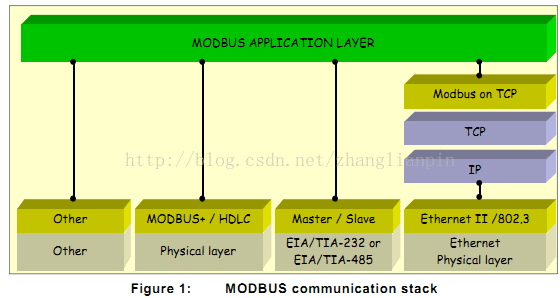
Modbus is an application layer message transmission protocol above layer 7 of the OSI model, which provides master/slave (or client/server) communication between different types of bus or network devices. At present, in order to continue to increase the support for the simple and elegant Modbus communication protocol, the Internet organization stipulates and reserves the system port 502 on the TCP/IP stack for accessing Modbus devices. The Modbus protocol stack model is as follows
Protocol
The MODBUS communication protocol currently exists for serial links, TCP/IP Ethernet, and other network versions that support the Internet Protocol. Most MODBUS device communication is connected through serial port (RS232/RS485) or TCP/IP physical layer
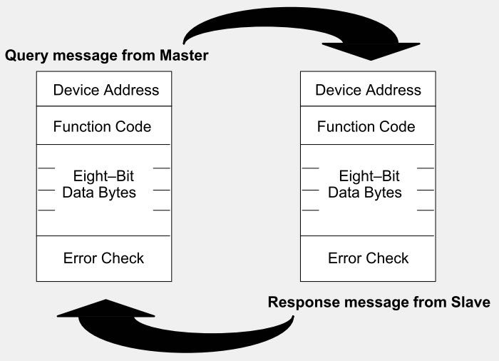
The MODBUS protocol is a single-master/multi-slave communication protocol, which is characterized in that there can only be one master device on the bus at the same time, but there can be one or more (up to 247) slave devices. MODBUS communication is always initiated by the master device. When the slave device does not receive a request from the master device, the slave device will not actively send data. The slave devices cannot communicate with each other, and the master device can only start a Modbus access transaction at the same time.
The master device can send a MODBUS request message to the slave device in two ways, that is, the master device can send a request message to a specified single slave device or all slave devices on the line, and the slave device can only receive the request message passively. Give a response message, that is, reply. The two modes are as follows:
Communication device
The Modbus protocol is a master/slave (Master/Slave) or client/server (Client/Server) architecture protocol. One node in the communication network is the Master node; other nodes that use the Modbus protocol to participate in the communication are Slave nodes, and each Slave device has a unique address. In a serial network, only the node designated as the master node can initiate a command (on Ethernet, any device can send a Modbus command, but usually only one master node device can initiate commands.
A MODBUS command contains the MODBUS address of the device to execute the command. All devices on the line will receive the command, but only the device with the specified address will execute and respond to the command (except for address 0, the command with the specified address 0 is a broadcast command, and all devices that receive the command will run, but there is no need to respond to the command). All MODBUS transmission messages contain error check codes to determine whether the arriving commands are complete. For example, basic MODBUS commands can instruct a MODBUS RTU device to change a certain value of its register, control or read an I/O port, and direct the device to return data in one or more registers.
MODBUS RTU Type
MODBUS Register Address
An important concept in the Modbus protocol is the register, and all data are stored in the register. Initially, the Modbus protocol borrowed the meaning of the register in the PLC, but with the wide application of the Mosbus protocol, the concept of the register is further generalized, and it no longer refers to The specific physical register may also refer to a memory area. The Modbus register divides the register into four parts according to the stored data type and their respective read and write characteristics. These four parts can be continuous or discontinuous, which is determined by the developer.
Register Category
Holding Register
Output parameters or hold parameters, certain parameters set when the controller is running, readable and writable
For Example:
Analog output setting value, PID operating parameters, variable valve output size, sensor alarm upper limit, lower limit, Inverter AC voltage range, Frequency Range etc.
Input Register
Input parameters, parameters obtained from external devices when the controller is running, readable but not writable
For Example:
analog input
Coil Status
Output port, the output state of the port can be set, and the output state of the bit can also be read. It can be divided into two different execution states, such as hold type or edge trigger type
For Example:
MOSFET Output,LED Display etc.
Input Status
Input port, change the input state through external settings, readable but not writable
For Example:
DIP switch, proximity switch, etc.
Modbus serial message frame format
Modbus RTU mode is only used for standard Modbus protocol searial network, It defines each byte of a message segment that is continuously transmitted over these networks, and determines how information is packaged into message fields and how it is decoded.
RTU Message Frame Format
The transmission device (master/slave device) places the Modbus message in a message frame with a known start point and end point, which requires the device receiving the message frame to start receiving at the start point of the message, and to know the message frame When the transfer ends. In addition, incomplete messages must be detected and error flags clearly set.
In usual, in serial port communication, 1 character includes 1 start bit, 8 data bits, 1 check bit (or none), and 1 stop bit (generally). In this way, in general, 1 character includes 11 bits
The meaning of baud rate in serial communication is the number of binary numbers transmitted per second. For example, the baud rate of 9600b/s means that 9600 bits of data are transmitted per second (ie 1000ms). Conversely, it takes 1000ms to transmit 9600 binary data.
Address Field
The address field refers to the address field in the Modbus communication frame, and its content is the address of the slave device. The address field of the Modbus message frame contains 1 byte (RTU mode)
The possible slave device address in the message frame is 0-247 (decimal), the actual address range of a single device is 1-247, and the master device gates the slave device by putting the slave device address to be contacted into the address field in the message. When the slave device sends a response message, the slave device puts its own address into the address field of the response, so that the master device knows which device has responded.
Address 0 is used as the broadcast address so that all slaves know
| Modubus Adress Range | ||
| 0 | 1-247 | 248-255 |
| Broadcast Address | Slave Device Address | Reserve |
Function Code Field
The function code is used to represent the message frame in the Modbus protocol
The function code field is composed of 1 byte, so its value range is 1-255 (decimal), for example, the commonly used function codes are 03, 04, 06, 16, etc. Among them, the function code of 03 is to read the holding register Content, the function of the 04 function code is to read the content of the input register, the content of the 06 function code is to preset a single holding register, and the content of the 16 function code is to preset multiple holding registers
Function code 03( 0x03 )
The 03 function code is used to read the content of the slave device holding register, and does not support the broadcast mode. The start address and number of holding registers to be read are specified in the message frame. The specific content and meaning of each address in the holding register is specified by the device developer.
Function code 04( 0x04 )
The 04 function code is used to read the content of the input register of the slave device, and does not support the broadcast mode. The start address and number of input registers to be read are specified in the message frame, and the specific content and meaning of each address in the input registers are specified by the developer
Function code 06( 0x06 )
The 06 function code is used to update the value of a single holding register of the slave device. This function code supports the broadcast mode. In the broadcast mode, the value of the same address of all slave devices will be uniformly modified
Function code 16( 0x10 )
16 function codes are used to set or write multiple consecutive address blocks (1-123 registers) of slave device holding registers, and support broadcast mode. In broadcast mode, the value of the same address of all slave devices will be uniformly modified . In this function code, the start address field is composed of 2 bytes, and the value range is 0x0000-0xFFFF; and the register quantity field is composed of 2 bytes, and the value range is 0x0001-0x007B
Data Field
The data field is closely related to the function code, and is used to store the specific data that the function code needs to operate. The data is in bytes, and the length is variable. For some function codes, the data field can be empty
Modbus Error Checking
In RTU mode, The message also contains an error check field, it adopts CRC ( Cyclical Redundancy Check ), The calculation object includes all bytes before the check field
Growatt Modbus Protocol type Download
Modbus ASCll Type
When the controller is set to communicate in ASCII mode on the Modbus network, each 8-bit (b) byte in the message will be sent as two ASCII characters. The main advantage of this method is that the time interval between character sending can reach 1 second without error.
In ASCII mode, the message starts with a colon (:) character (ASCII code is 0x3A) and ends with a carriage return and line feed character (ASCII code is 0…9, A…F). Modbus devices on the network continuously detect the “:” character. When receiving a colon, each device enters the decoding stage and decodes the next field (address field) to determine whether it is sent to itself. The maximum time interval between sending characters in the message frame cannot exceed 1 second, otherwise the receiving device will think that a transmission error has occurred.