Datalogger will upload many important data into server. They are stored in History data. You can download it and read key parameters.
1. How to download History data from server
Please note that just Distribuotr or installer or Our service engineer account can download history data.
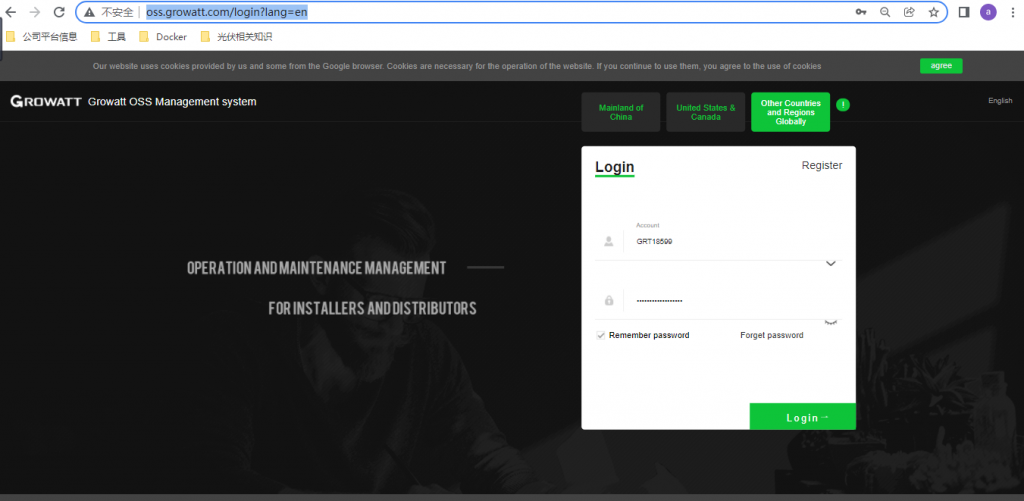
a. Access OSS account via http://oss.growatt.com/login?lang=en
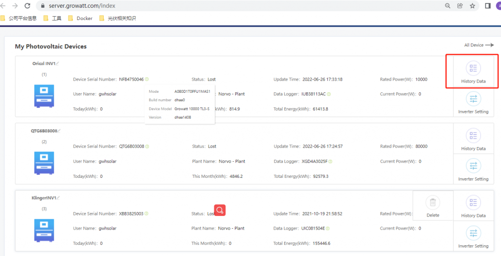
b. Download History data
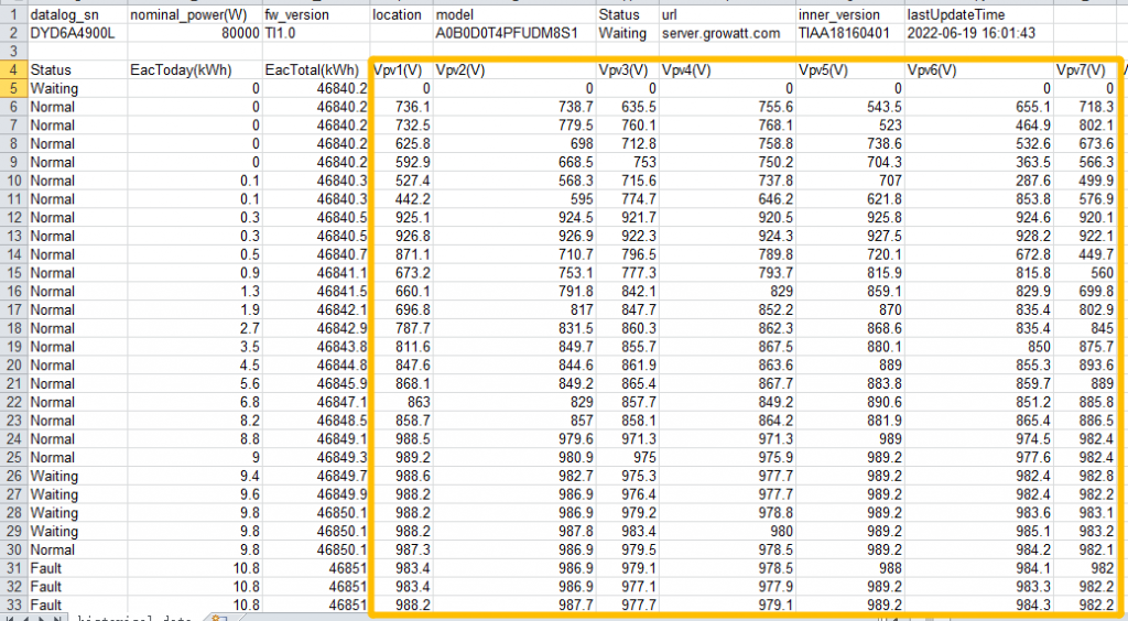
c. History data as excel form
d. Introduction about all important data in histoy data

1 ) model A0B0D0T4PFUDM8S1
A0
Safety Type, The high byte part which is Used with low byte Sx
B0
SVG/APF enable; Dual communication/anti-backflow enable (M3)
一般默认不开启,目前仅1500V机器有SVG功能 逆变器APF的主要功能是滤除谐波电流,实现动态补偿无功和电压波动,以及抑制谐振,从而提高功率因数,改善供电系统的安全性和节能降耗。
Dx
D0: Neutral Inverter
D1: Standard Inverter
D2: INTERL_BRAS
D3: CHNT
D4: Universal Inverter
D5-DF: other models, etc., different models are different
Tx
Function mode selection
Bit0: PV-ground mode
Bit1: PID enable
Bit2: String monitoring enable
Bit3: reserved
Px
Safety protection enabled, Use Bit to represent different security protections
Bit0: ISO enable
Bit1: DCI enable
Bit2: GFCI enable
Bit3: Customer protection scope customization enable
Ux
Three-phase rated voltage range, MPPT channels, AFCI enable
BIT0-BIT1: AC voltage level
(0: AC277V, 1: AC230V, 2: AC288V, 3: AC127V)
BIT2: Number of MPPT channels
(0: Six way 1: Seven way)
BIT3: AFCI enable
Mx
power segment
Different models of power segment
MAX project
MB: 25KW
M3: 30KW
MC: 35KW
M4: 40KW
M5: 50KW
M6: 60KW
M7: 70KW
M1: 75KW
M8:80KW
M9: 90KW
MA: 100KW
Sx
the low byte part of types of safety standards which is used with high byte Ax
The safety standard type AxSx is 8-byte data.
Current safety regulations such as safety standard Model corresponding table
2 ) Vp1-Vpx
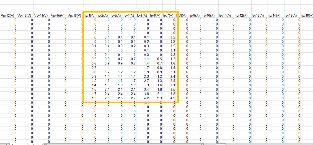
3 ) Ipv1(A)-Ipv7(a)
It shows MPPT current of Every PV string.
3 ) ppv1(w)-ppv7(w)
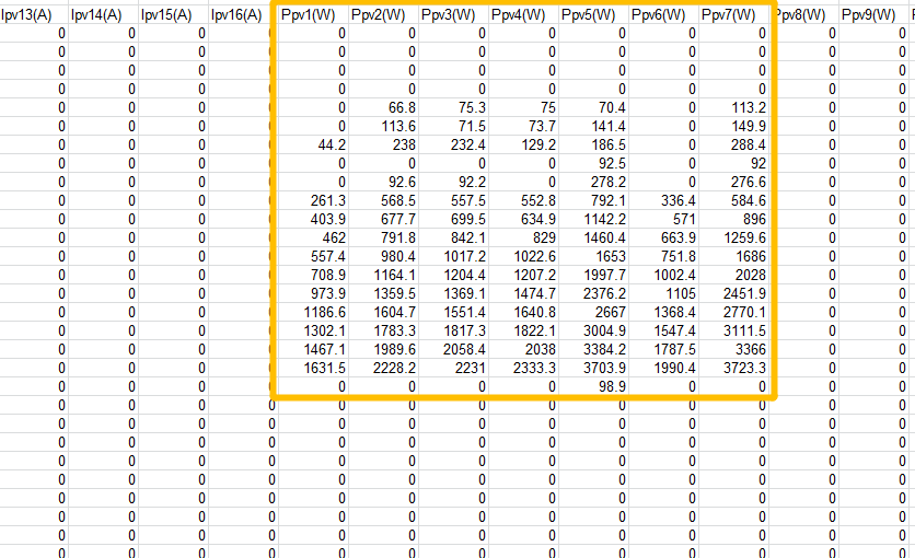
It shows Ppv1(w)-Ppv7(w)
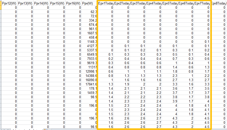
4 ) Epv1Today-Epv7Today
5 ) vacRS(V), VacST(v), vacTR(V)
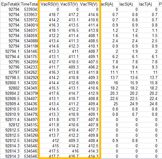
VacRS is the line voltage between R and S phase
VacST is the line voltage between S and T phase
VacTR is the line voltage between T and R phase
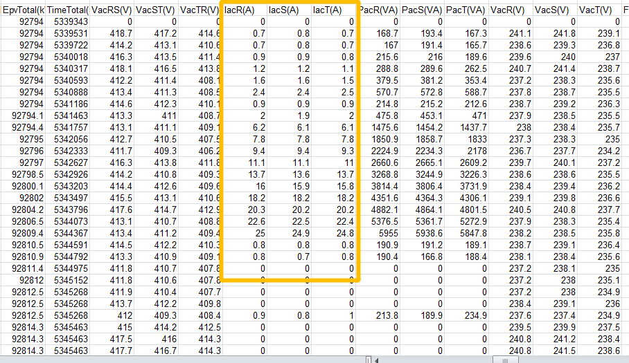
5 ) IacR(A), IacS(A), iacT(A)
6 ) PacR(vA), PacS(vA), PacT(vA)
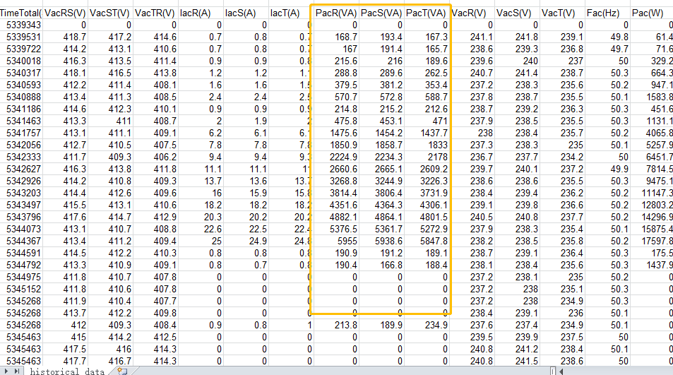
PacR(vA), PacS(vA), PacT(vA) shows apparent power
7 ) VacR(v), VacS(v), VacT(v)
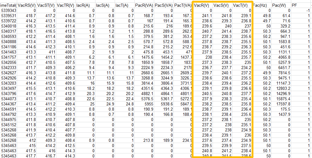
VacR(v), VacS(v), VacT(v) shows Phase voltage
8 ) Fac(HZ)
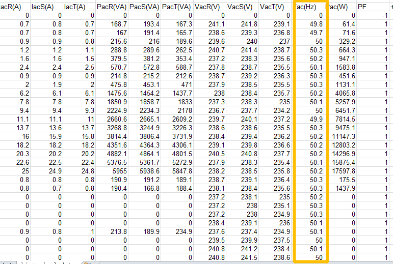
9 ) Fac(HZ)
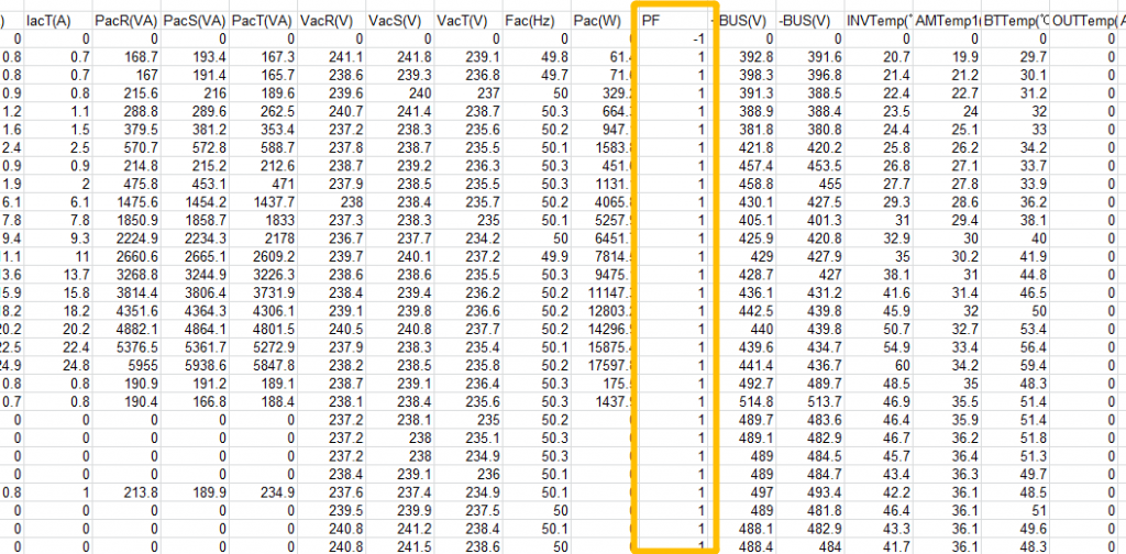
PF shows power factor value: -1~1
10 ) BUS+ ,BUS-
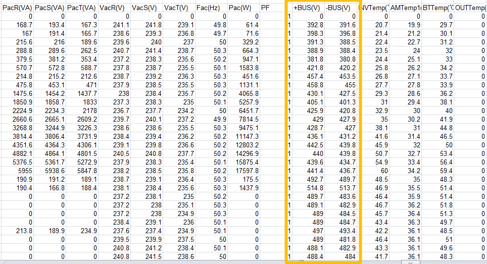
Normal BUS voltage value is 200-1000V
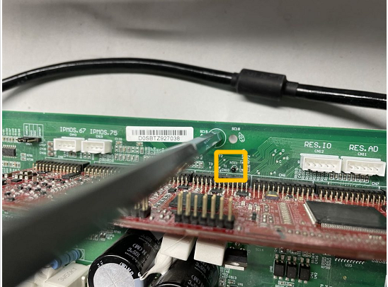
11 ) INVTemp, AMtemp1, BTTTemp
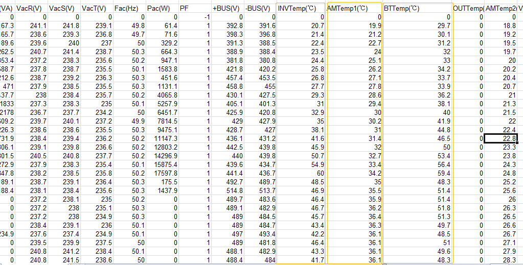
INVTemp:
INV circuit ( DC-AC ) has 3 INV module ( Temperature sensors have integrated in it)
BTTemp
BTT is abbreviation of Boost Circuit, which has 3 Boost modules( Temperature sensors have integrated in it )
AMTemp1(℃)
Ambient Environment Temperature
AMTemp2(℃)
12) FaultCode
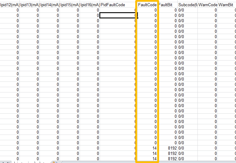
You can search fault code info. from user manual. based on the fault code.
13) FaultBit
Faultbit可以解读出多个故障,故障码只会显示一个故障
faultcode是根据优先级显示当前优先级最高的故障,faultbit是显示所有故障新,可能会同时发生过个故障,用来售后分析的
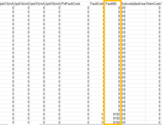
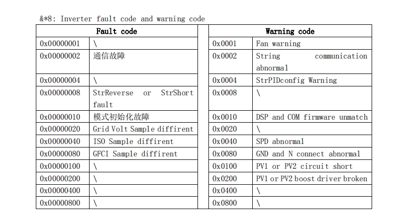
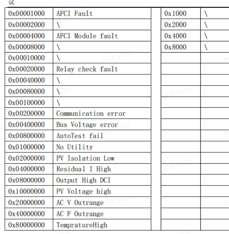
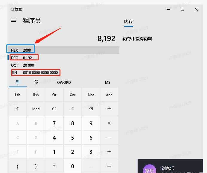
For Example: Hex value is 2000, you can search code from above form
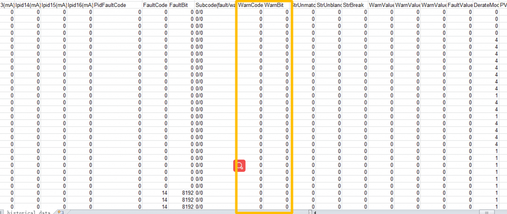
14) WarmCode, WarnBit
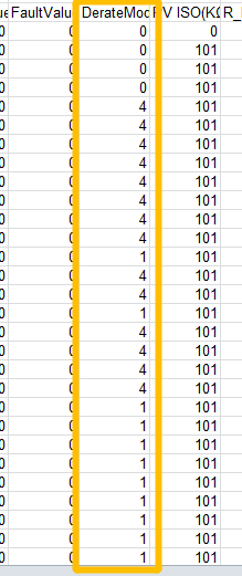
15) DegradeMode
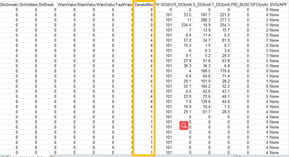
For more details, please visit https://www.amosplanet.org/degrade-mode-on-max-series-introduction/ password; degrade20220625
16) PV ISO
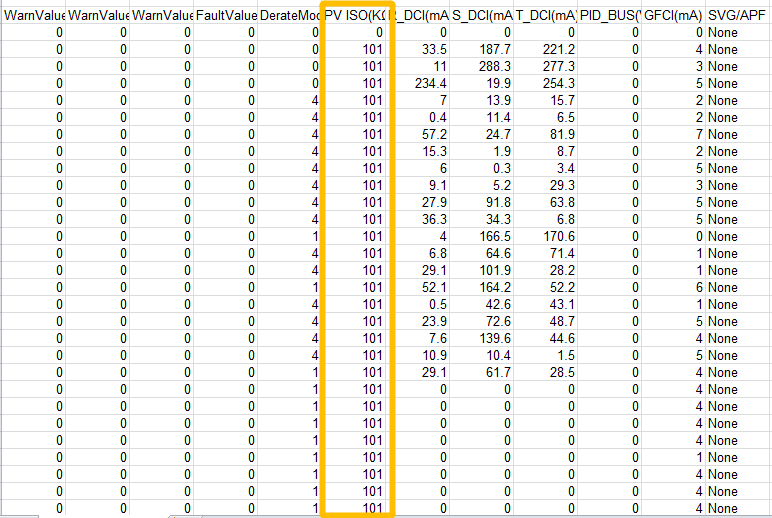
PV ISO value is used to confirm earth issue on PV side. Once it exceeds 50KΩ , the inverter will alarm. Normal value is 65532
17) R_DCI, S_DCI, T_DCI
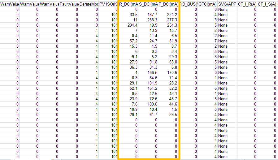
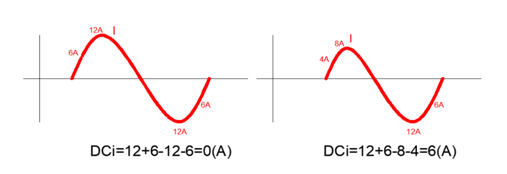
Direct Current Injection), The meaning of DCI is that in one cycle, positive wave value of AC current +negative wave value of AC current =0 for normal situation, once DCI value is not 0, it means the inbalance between positive wave and negative wave is occuring. It may be caused by Grid or inverter by itself.
DCi explanation:
DCi goes 0 when the sum of sampling currernts is zero,
otherwise there will be a DCi bias value showing in history data.
The standard DCi value is less than 0.5% of the maxinum current in AC output at fulll load.
It will affect the AC output quality if an inverter produces high DCi .
17) PID_BUS
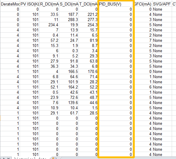
PID circuit is like BOOST circuit, which is used to promote the voltage between positve and earth, this BUS voltage is formed by PID circuit.
18) GFCI
Ground fault circuit interrupter
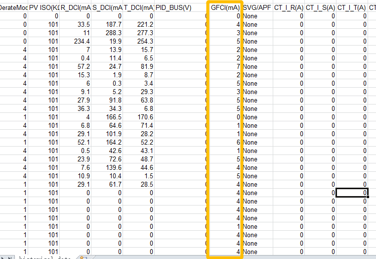
GFCI is used to judge if AC side has earth issue, the principle is like RCD, once 3 phase inbalance, it will detect the current. In usual, it should be less than 30mA.
level1: leakage current>30mA-off grid reaction<200ms
level2: leakage current>60mA-off grid reaction<60ms
level3: leakage current>150mA-off grid reaction<20ms
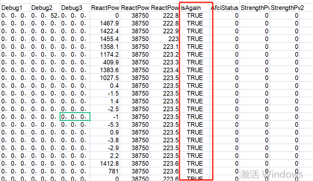
19) Debug1
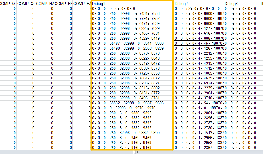
Debug1 value is from 28067 Chip
Example: 0,0,0,250,32998,0,7434,7858
Input Register 182: 0
it means Boost software Over current protection count, once triggered, it will increase 1
Input Register 183: 0
It means Boost software Over current channel , the specifical route number last time
Input Register 184: 0
Over current Triggering value last time
Input Register 185: 250
Boost current limitation value
Input Register 186: 32998
System status High bits
Input Register 187: 0
System status Low bits
Input Register 188: 7434
limitation value of The first PV route
Input Register 189: 7858
BOOST side BUS voltage limitation value
19) Debug2
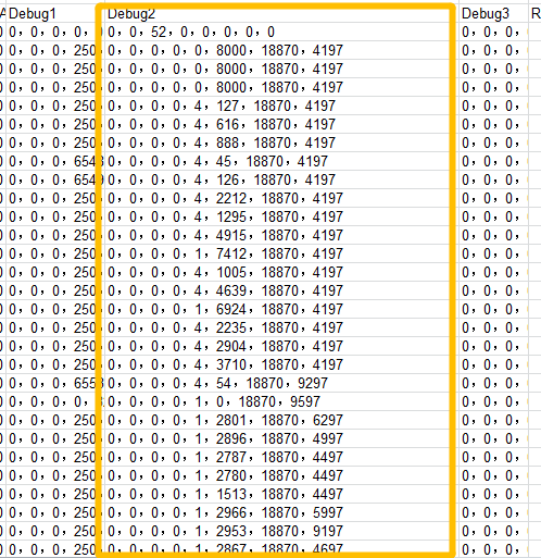
Example: 0,0,0,0,4,127,18870,4197
Input Register 190: 0
It means INV OCP( Over Current Protection ) count, once triggered, it will increase 1
Input Register 191: 0
It means BOOST OCP( Over Current Protection ) count, once triggered, it will increase 1
Input Register 192: 0
Driving fault count, once triggered , it will increase 1
Input Register 193: 0
INV software OCP( Over Current Protection ) count, once triggered , it will increase 1
Input Register 194: 4
Degrade mode, when degrading , the value is not 0. It equals vaule on Degratemode column
Input Register 195: 127
When degrading, it will limit the value, if not, the value is 80KW
Input Register 196: 18870
RelayCheck steps and time
The ten thousand digit indicates that the inverter PWM has been detected and the OK mark is displayed, the thousand digit represents the number of steps, and the following one represents the timing( like 870 ) .
For more details about meaning of the timing , please find Relay fault in https://www.amosplanet.org/the-meaning-of-max-50k-80k-tl3-malfunction-and-warning-code/ password: meaning20220625
Input Register 197: 4197
SPS malfunction Count, once triggered, it will increase 1
19) Debug3
it is useless
19) ReactPower(Var)
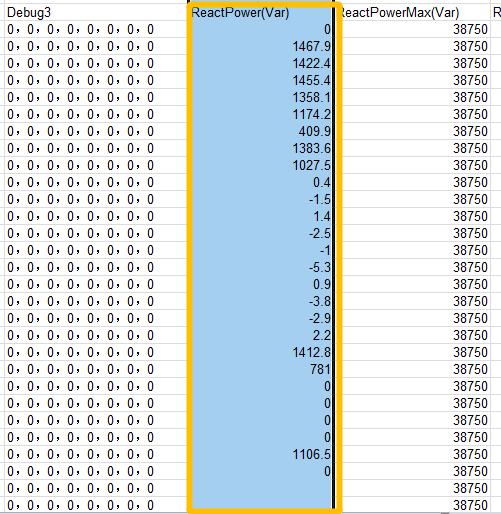
For more info. about reacitve power , please read the post https://www.amosplanet.org/how-to-adjust-to-active-power-rate-reactive-power-rate-pf-on-grid-inverter/
password: explore20220621
20) isAgain
True -uploading missed data after being offline