MAX 50K-80K TL3 Malfunction AND WARNING CODE
1. How to Read error code
Error code
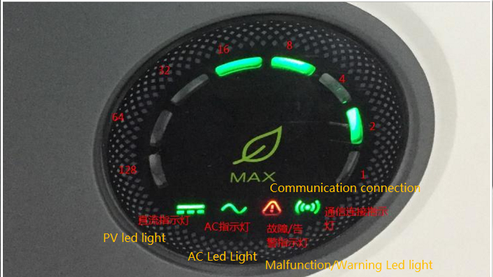
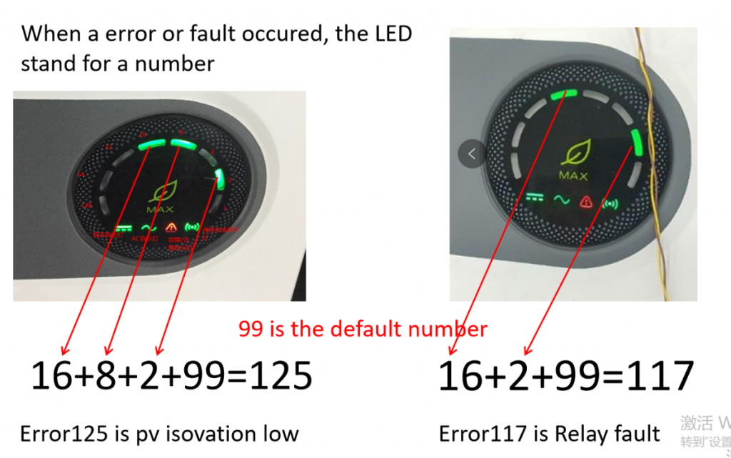
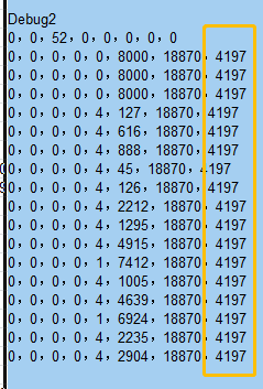
From right to left side, there are 8 led lights, it represents 1 ,2, 4, 8, 16,32, 64,128. two to the 0 power, two to the 1st power etc. Above picture, Fault code = 2^2+2^3+2^4+99=127
When fault occurs, inverter will stop running and Malfunction/Warning led light will be on constantly. 8 led light will work based on fault state. 1 represents on, 0 represents off.
2. Error code Meaning
1) Error 101
Meaning: Communication fault
101是最高优先级的; 101 fault has highest priority in error codes
LED Display 0000 0010
Triggering Condition:
a. STM32 on M3 board doesn’t receive data from control board over 10s
b. 28075 OR 28067 doesn’t receive data from M3 board over 5s
c. SPI Connected 28075 and 28067 if fail over 1s
Checking method
a. Check if firmwares are correct on the inverter
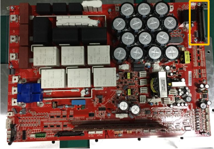
b. Check the connection wire from M3 board to Mainboard

c. If still can’t work, you can try to replace control board from normal inverter.
d. If still can’t work, you can try to replace IO board from normal inverter.
f. If still can’t work, you can try to replace M3 board from normal inverter.
Solution:
Upgrade the inverter or Replace control board, IO board or M3 board
Pleaset note that If MAX inverter has AFCI funciton, AFCI module also can cause 101 fault. You can disable AFCI function on inverter, try to set:
Register address 541 : Value: 160
It means to disable AFCI function
If it can’t work, please set new model number and disable AFCI function
For Example:
A0B0D0T0PFUDM7S1
U has defined AFCI function
BIT0-BIT1: AC voltage level
(0: AC277V, 1: AC230V, 2: AC288V, 3: AC127V)
BIT2: Number of MPPT channels
(0: Six way 1: Seven way)
BIT3: AFCI enable
0 represents 00, 1 represents 01, 2 represents 10, 3 represents 11
UD means U 1101, from right to left, the third bit is Bit2, the fourth bit is Bit3
2) Error 102
Meaning: Sample of main DSP and slave DSP are inconsistent
LED Display 0000 0011
Triggering Condition:
When PV Sampling,Positive and negative bus sampling,3 phases AC Voltage sampling,GFCI,ISO Sampling between main DSP28075 and DSP28067 have big difference , then it will alarm the fault
Checking method:
a. Try to restart the inverter
b. Try to read input register 181, bit9-bit12
c. According to value on 181 register address, confirm which sampling signal is abnormal
Solution:
Replace IO board or Control board
3) Error 106
Meaning; PVCurrSampleFault
LED Display 0000 0111
Triggering Condition:
PV current is greater than 10A before connecting to the grid
NON INV State , if PV current sampling is greater than 10A, and last for 5 seconds, it will trigger the fault; If PV current sampling is lower than 10A, and last for 20 seconds, the fault can be cleared automatically.
Solution:
a. Check 50PIN Drive Row Wire
b. Check if mainboard is normal
c. Check if PV input board is normal ( You can try to replace it)
b. Try to upgrade the inverter
c. Try to swap control board from normal inverter
d. Try to replace IO Board
Case Caring:
MAX 70KTL3 LV QSGCCGW003
Client found that IO board was burnt, ,after replacing IO board, it alramed 106 fault, when taking out mainboard, driving cirucit of mainboard is burned.
So 106 fault may be caused by mainboard. PV current sampling circuit is on mainboard
4) Error 107
Meaning; ACCurrSampleFault
LED Display 0000 1000
Triggering Condition:
NON INV State , AC current sampling is greater than 20A or MAX average AC Current 3.5A, and last for 5 seconds. it will trigger the fault; If these conditions are not satisfied and last for 20 seconds., fault will be cleared .
Solution:
a. Try to upgrade inverter firstly
b. Try to swap control board from normal inverter
c. Try to replace IO board
5) Error 108
Meaning; SPS Power Fault
LED Display 0000 1001
Triggering Condition:
Hardware signal detection error, corresponding to GPIO94, low level error
(The current version will not report an error, and the count can be read in the debug information)
checking method:
Check if PV input voltage, connection wire, switch are normal
Solution:
a. Check if PV input and Grid voltage is normal
b. If above is normal, Try to upgrade the inverter
c. If still not ok, Try to replace IO board
d. If still not ok, try to replace control board
6) Error 112
Meaning; AFCI ARC Discharge
LED Display 0000 1101
Triggering Condition:
AFCI module Detects ARC malfunction,the previous 2 times ,it will shut down inverter and detect it again, until third time, inverter will alarm (GPIO32 status pin,GPIO27 test pin)
checking method:
a. Check if PV system has ARC phenomenon, if yes, check all PV strings.
b. If PV system is ok, try to replace IO board
Solution:
a. Check PV system
b. Check AFCI Module
c. replace IO board, control board
6) Error 113
Meaning; IGBT drive fault
LED Display 0000 1110
Triggering Condition:
Hardware Signal detecting alarm, corresponding to GPIO86,low level will have the fault.
checking method:
a. Check if Driving power has 15V or -7V
b. Check if IGBT is broken
Solution:
a. Try to swap control board from normal inverter
b. Try to swap IO board from normal inverter
c. Try to replace mainboard
7) Error 114
Meaning; AFCI module detecting fault
LED Display 0000 1111
The AFCI module fails self-test. The first two tests will be turned off and tes it again, until an error will be reported for the third time (GPIO32 is the status pin, and GPIO27 is the test pin).
checking method:
a、Confirm if AFCI module is connected;
b、Confirm if AFCI module is normal
Solution:
Replace AFCI or IO board
7) Error 115
Meaning: INV OCP Fault ( INV Over current Fault )
Only when inverter is on waiting state, 115 fault will occur.
7) Error 117
Meaning; Relay fault
LED Display 0001 0010

There are 2 situations that Detect Relay status
a. Before inverter produces wave , inverter will detect the voltage between AC output relay and input relay, once the volage is lower than 120V, it will trigger the relay fault
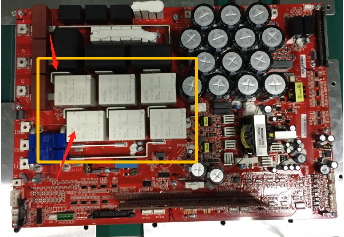
b. When inverter produces wave , inverter will detect the voltage between AC output relay and input relay, once the voltage is greater than 50V, it will trigger the relay fault
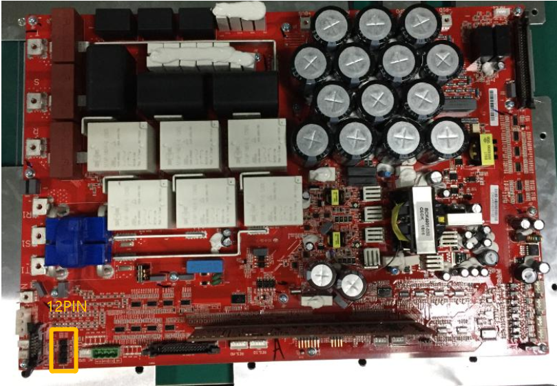
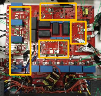
How to judge which relay is faulty via USB-WIFI
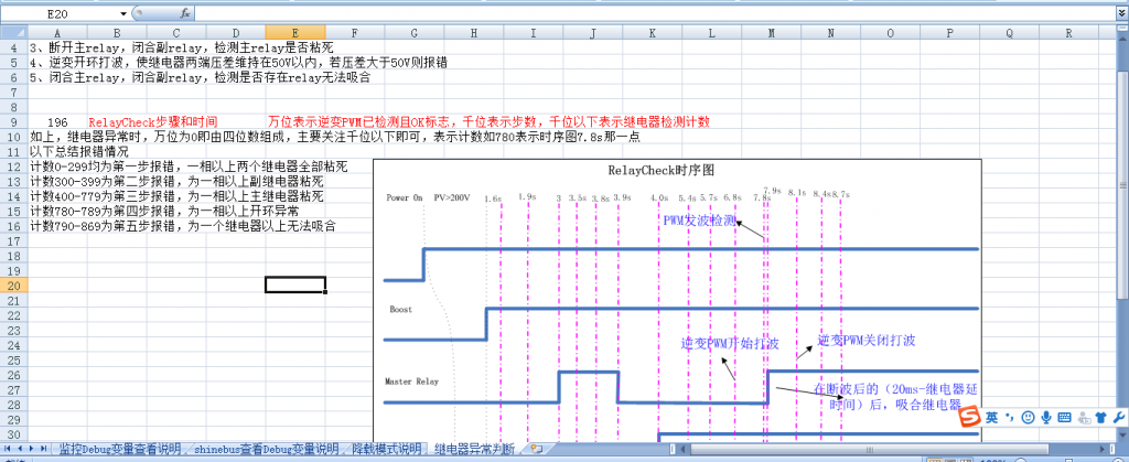
Read 196 register address value via USB-WIFI
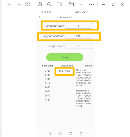
The value is 7789 (ignore the first bit 7), just read 789, then find it in above picture
0-299 means fault occurs on the first step , more than 2 relays on 1 phase at least are adhered.
300-399 fault occurs on the second step, slave relay on 1 phase at least are adhered.
400-779 fault occurs on the third step, master relay on 1 phase at least are adhered.
780-789 fault occurs on the fourth step, open circle abnormal on 1 phase at least
790-869 fault occurs on the fifth step, more than 1 relays can be turned on.
Checking method:
a. Check earth issue on AC side including on site, outside site. ( It is common on site )
b. Based on the value you read on 196 register address, check parallel wire between IO and control board
b. Check if relay is broken
d. check the driving circuit of relay
e. check relay sampling circuit
Solution:
a. Check earth issue on site and outside site firstly, repair damaged AC wires
b. Replace IO board or control board
8) Error 120
Meaning: PV-N-PE Detecting fault
LED Display 0001 0101
1、When model T position bit1 Enabled and has no grid malfunction, then it will have the warning
2、On NON INV state,NE voltage difference lower than 70V, and alram lasts for 1 second, lower than 120V and alram lasts for 2s, fault will be cleared.
Checking method:
Check if N and PE is good
Solution:
9) Error 121
Meaning; CPLD chip is abnormal
GPIO77 signal low constantly or CPLD has no communication
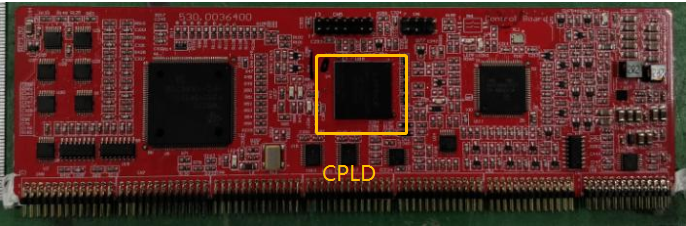
Checking method:
Observe if led light of CPLD is blinking
Solution:
Replace control board
9) Error 122
Meaning; Bus Fault/Bus voltage abnormal
LED Display 0001 0111
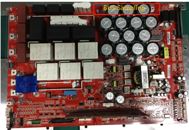
INV BUS Sampling
a. Half BUS voltage is greater than 540V or BUS voltage is greater than 1070V
b. INV state half BUS voltage is lower than 220V or bus voltage is lower than 450V
c. after the fault occurs, half of BUS voltage is lower than 520V and last for 1min, then fault can be cleared
BOOST BUS Sampling
a. Half of BUS voltage is greater than 540V or Bus voltage is greater than 1070V
b. INV state half of BUS voltage is lower than 220V or BUS voltage is lower than 450V
c. PV is greater than BUS voltage for 50V and last 200ms, OR positive BUS voltage and negative BUS voltage have the 100V difference , and last for 200ms, when BUS voltage sampling becomes normal and last for 200ms, fault can be cleared.
d. When fault occurs, Half of BUS voltage should be lower than 520V and current fault is not 3, And abnormal INV BUS voltage has been cleared and last for 1 min, then all fault can be cleared.
Checking method:
a. Check if PV system meets max 1100V
b. Check if PV input and Boost inductor Wire have been connected correctly.
c. Check BUS voltage Sampling circuit
d. Confirm if DCI value is a little bit bigger, it may cause inbalance on bus voltage
Solution:
a. Check PV system
b. Try to replace IO board or mainboard
10) Error 124
Meaning; No AC Connection
LED Display 0001 1001
Triggering conditon:
a. all 3 phase line voltages are lower than 173.2V
b. doesn’t meet a condition, and last for 2 seconds, fault will be cleared.
Checking method:
Check if AC connection wire is normal
Solution:
a. Check grid state
11) Error 125
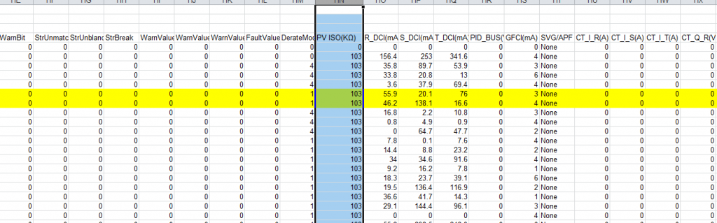
Meaning; PV Isolation Low
Inverter just detect PV isolation when starting, in other state, it won’t do that.
LED Display 0001 1010
Triggering condition:
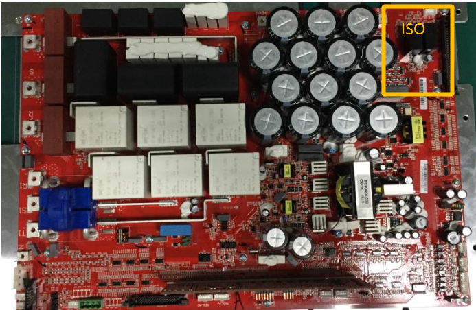
a. ISO detecting resistance is lower than 50KΩ, then it will have the fault
b. When fault occurs, Detecting ISO resistance is greater than 70KΩ, then fault will be cleared automatically
Checking method:
a. Please read the post about how to check earth issue on PV system: how-to-check-earth-issue-on-pv-side
b. Check if PV input board, mainboard , IO board, control board is normal
Solution:
a. Repair broken PV wire on PV system
b. Uncover the inverter and Replace abnormal board
12) Error 126
Meaning; Leakage current too high
LED Display 0001 1011
Triggering condition:
a. The effective value of the GFCI current is greater than the protection value (theoretical requirement: apparent power * 0.01mA) for 200ms to report an error
b. The GFCI current jumps up to 150mA, and last for 20ms
c. The GFCI current jumps up to 60mA, and last for 60ms
d. GFCI current jump up to 30mA, last for 200ms
Checking method:
a. Check AC output input wire
b. Check GFCI Sampling Circuit
Solution:
Replace IO board
12) Error 127
Meaning; Output DC current too high
LED Display 0001 1100
Triggering Condition:
1、PF (it comes from Model number),DCI is greater than 2A,( the time when fault occurs is related with safety rule, safety rule *5
2、Non PF mode,DCI is greater than protection value(apparent current *0.5%)
Checking method:
a. Check if AC voltage, current is normal
b. Check if IGBTs of INV and driving circuit are normal
c. Check DCI Sampling Circuit
13) Error 128
Meaning; PV Voltage High
LED Display 0001 1101
Triggering Condition:
a. PV voltage is greater than 1070V and last for 200ms
b. PV voltage is lower than 1000V and last for 2s, fault will be cleared automatically
Checking method:
Please disconnect DC and AC, and make sure PV voltage of each string is lower than 1000V
Solution:
If PV input voltage is greater than 1000V, you can reduce solar panels.
14) Error 129
Meaning; Grid voltage fault
LED Display 0001 1110
Triggering Condition:
a. Check the safety table to confirm the protection value and protection time of the first, second and third order overvoltage and undervoltage respectively. If the grid voltage meets the error condition and time, the fault will be triggered.
b. The 10min average value of the grid voltage is greater than the safety table query value to trigger a fault
15) Error 130
Meaning; Grid frequency fault
LED Display 0001 1111
Triggering Condition:
a. Check the safety table to confirm the protection value and protection time of the first-order, second-order and third-order over-frequency and under-frequency respectively. If the grid frequency meets the error condition and time, the fault will be triggered.
b. The power grid frequency changes more than 2.5Hz within 1s to trigger the fault, the change value is less than 2.5Hz and the fault is cleared by saving 2s within the first-order over-under-frequency range
Checking Method
a. Check if AC frequency is abnormal, Grid is normal
b. Shinebus has read the undervoltage frequency to confirm whether it has been accidentally set
Warning code
When the machine has an alarm, it does not affect the normal power generation of the machine, so it is necessary to observe whether there is a prompt when the machine is running during maintenance.
It can directly display the alarm through the LED light (but you can’t see the specific alarm code), you need to monitor it through shinebus at this time and See the specific alarm code
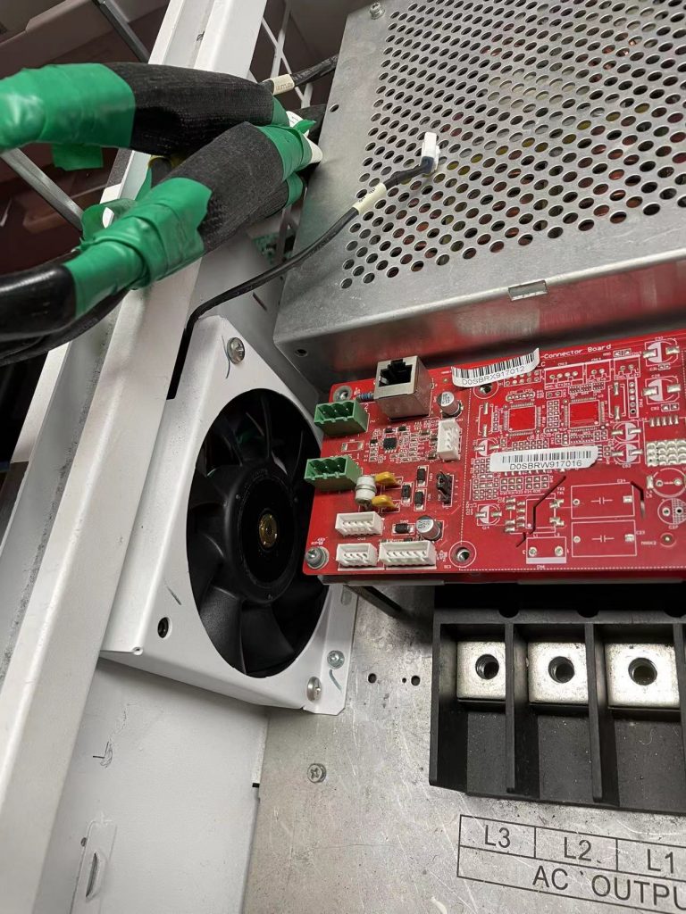
15) Warning 100
Meaning; Fan abnormal
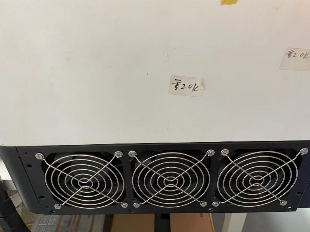
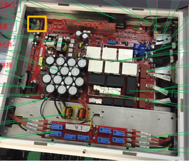
Triggering Condition:
a. The normal operating frequency range of external fans (FAN1-FAN3) is 70Hz-80Hz
b. Internal fan (FAN4) normal operating frequency range 40Hz-50Hz
c. If the frequency is not within the range during operation, an error will be reported, and if the frequency is within the range after operation, the alarm will be cleared.
Checking Method:
a. Read the input register No. 229 to distinguish the alarm fan number. 1, 2, 4, and 8 respectively indicate the error bit of the four fans. For example, FAN1 and FAN3 report an error, return value is 1+4=5, and the normal reading is 0. , no fan abnormality
b. Check if fan power supply is normal
c. Check fan driving and detecting Circit
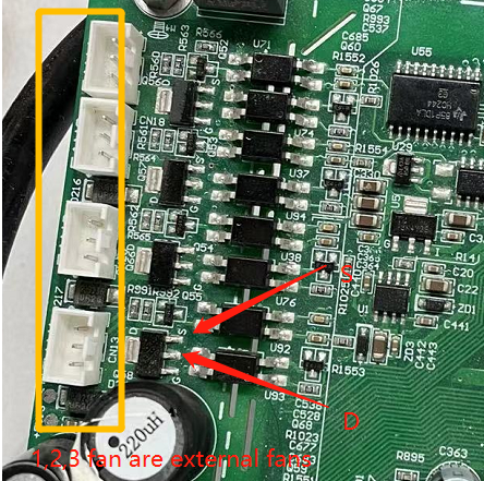
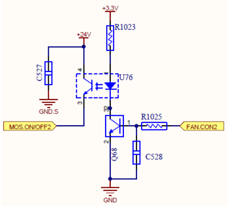
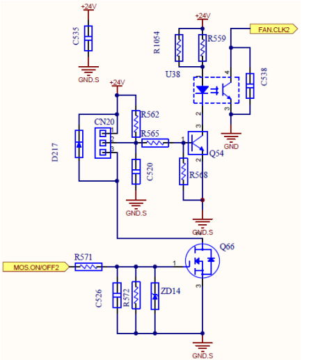
Test D and S pin , ever fan has 3 wires, including positive, negative, signal line.
16) Warning 103
Meaning; NTC Broken
Triggering Condition:
a. One of BOOST and INV temperature is less than 5℃, and the other is greater than 70℃
b. Ambient temperature is 20°C higher than one or both of BOOST or INV temperature
c. The current power is less than 10%, and the inverter temperature is greater than 115.3°C or the BOOST temperature is greater than 88.3°C or the ambient temperature is greater than 87°C, if one of them is satisfied, an alarm will be issued
d. If the above conditions are not met, the alarm can be cleared
Checking method:
Check the NTC sampling module
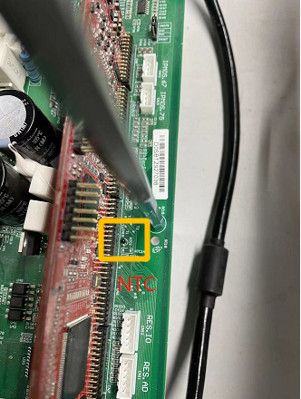
Solution:
Replace IO board or mainboard
17) Warning 105
Meaning; Over Temperature
Triggering Condition:
If the ambient temperature of the DSP or M3 cabinet is greater than 87°C, and if the ambient temperature is lower than 78°C, the alarm will be cleared.
Checking method:
Check if the ambient temperature is too high
18) Warning 106
Meaning; SPD abnormal
Triggering Condition:
Hardware signal detection error, AC SPD corresponds to GPIO67, PV SPD corresponds to GPIO68, low level error
Checking method:
a. Read Input 180 register, 1 means AC SPD is abnormal, 2 means DC SPD is abnormal, 3 means both are abnormal, 0 means no abnormality
b. For machines with lightning arresters, it is necessary to check whether the lightning arresters are normal;
c. Check AC WB and M3 cables;
d. Check the fault detection circuit of the lightning arrester;
19) Warning 107
Meaning; NE abnormal
N means real Neutral, The voltage between Neutral and Earth can reflect 3 phase inbalance
Triggering Condition:
a. After the holding register 235 is enabled and there is no grid fault, the alarm will be detected
b. In the waiting state, if the NE voltage difference is greater than 30V for 1s, the alarm will continue, and if it is less than 20V for 2s, the alarm will be cleared.
Checking method:
Check Neutral or Earth wire
20) Warning 108
Meaning; PV Circuit short
Triggering Condition:
a. The sampled PV voltage is less than 30V, but the PV current is greater than 5A. If the conditions are met, an alarm will be issued.
Checking method:
a. According to the table Warning Value method, the specific number of MPPT can be determined, that is, Input 179 register bit0-bit7
b. Check whether PV strings or the line is short-circuited
21) Warning 109
Meaning; PV boost driver broken
Triggering Condition:
In the inverter state, if the duty cycle of the software loop output is greater than or equal to the upper limit of the PWM limit and the duty cycle of the loop output is 20% larger than the theoretically required duty cycle, the condition will be alarmed, but the alarm will not be cleared.
Checking method:
a. According to the table Warning Value method, the specific number of error can be determined, that is, bit8-bit15 of Input 179 register
b. Check whether the boost driver or mosfets on Boost in the 6-way is abnormal
22) Warning 110
Meaning; String abnormal
Triggering Condition:
a. In the inverter state, the string voltage is less than 15V and the string current is less than 500mA
b. In the non-inverting state, the string voltage is less than 15V and the string current is less than or equal to -2A
c. one of 1 and 2 conditions are satisfied, alarms after 5min, if the string voltage exceeds 200V for 1min, clear the alarm
Checking method:
a. According to the table Warning Value method, the specific number of error can be determined, that is, bit0-bit15 of Input 178 register
b. Check whether the string is reverse or short-circuited
c. Check whether the sampling is abnormal
23) Warning 111
Meaning; U disk overcurrent protection
Triggering Condition:
U disk overcurrent protection
Checking method:
Check whether the U disk port is short-circuited, or whether an abnormal USB terminal is externally connected.
24) Warning 112
Meaning; Exporting Current Limitation Function is abnormal.
Triggering Condition:
a. After the single machine anti-backflow is enabled, the time of no communication with the meter exceeds the anti-backflow failure time (default 120s)
b. After multi-machine anti-backflow is enabled, no communication with the shinemaster exceeds the anti-backflow failure time (default 30s)
c、After the multi-machine anti-backflow is enabled, the Shinemaster and the meter have no communication conditions ( judged by the Shinemaster), and the Shinemaster issues the anti-backflow failure command
d. After the multi-machine reactive power scheduling is enabled, no communication with the shinymaster exceeds the reactive power scheduling failure time (default 120s)
e. After the multi-machine reactive power scheduling is enabled, if there is no communication between the Shinemaster and the meter (judged by the Shinemaster), the Shinemaster issues the reactive power scheduling invalid command
f. Common registers and alarm codes for reactive power scheduling and anti-backflow, the two functions are not allowed to be enabled at the same time
Checking method:
a. Confirm whether the anti-reverse flow is enabled by mistake, the single machine corresponds to the No. 122 register, and the multi-machine corresponds to the No. 306 register
b. Check whether the anti-backflow port communication between inverter and smart meter is normal
c. Confirm whether reactive power scheduling is enabled, that is, query whether the holding register 89 is 7