How To adjust to active power rate, reactive power rate, PF
1. what’s active power rate, reactive power rate, PF
Active power rate
Power contains active power and reactive power. , the instantaneous power of AC current is not a constant value, the average value of power in a cycle is called active power, which refers to the power consumed by the resistance part in the circuit, the symbol of active power is represented by P, and the unit is watt (W), Kilowatt (kW)。
Active power rate means active power production percentage of total active power
Reactive power rate
Reactive power contains Inductive reactive power and capacitive reactive power, Reactive power rate is used to set Inductive reactive power or capacitive reactive power rate.
Inductive reactive power
Current wave leads voltage wave . Inductive reacitve power is used to create magnetic field. Inductive load needs to consume inductive reacitve power
Inductive load
Some applicances like transformer, motor etc. needs to consume Inductive reactive power, which called inductive load which is that current wave lags voltage wave.
capacitive reactive power
Current wave lags voltage wave . Simply speaking, there is no sudden change in voltage during charging and discharging for capacitive reactive power , and the corresponding power factor is negative. Capacitive reactive power can be used when Grid voltage is too high

capacitive Load
Some applicances like capacitor etc. , called capacitive Load which is that current wave leads voltage wave.
PF
Power Factor (cosφ) is the cosine of the angle between the current and the voltage phase difference (usually the current lags) in an AC circuit
The higher the power factor, the higher the utilization of electrical energy. The highest power factor is 1, which means that the phase difference is zero, and all the electric energy is consumed by the pure resistance load; the lowest power factor is 0, which means that the phase difference is 90 degrees, all the electric energy is wasted on the line, and is not used by the load at all.
For one device, if it inputs active power, the active power is positive; otherwise, if it outputs active power, the active power is negative. Therefore, the value range of the power factor is: -1~+1
2. How to set active power rate, reactive power rate, PF
Method 1:
1) Access server.growatt.com via end user account

2) Click ” Inverter Setting “

3) Set Value

Not Memory: it means that when you set the value on Not memory, once you switch off inverter, it will recover back defaul value.
Memeory: It means that when you set the value on memory, it will be stored forever.
PF:It is used to set PF value , the range is -0.8~0.8 it is on reactive power rate row , same meaning with PF
KEY: growatt+today’s date like growatt20220611
Method 2:
1) Access server.growatt.com via end user account
2) Click ” Inverter Setting “
3) Set Value on register address
You can get related register address from https://www.amosplanet.org/download-modbus-protocol-type-of-grid-inverter/ based on your inverter model
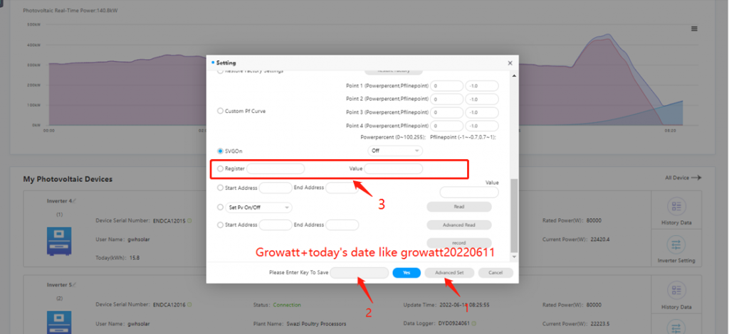
4) find register address about activate or reactive power from modbus protocol
Method 3:
If it can’t be operated remotely, you can set it via Shinebus tool locally. USB-485 tool and driving program needs to be prepared in advance.
Tool:
USB-485 or USB-232-485

Driving program for USB-485
Please download it from your USB=485 manufacturor offical website and install it on your laptop. For USB-232-485, you don’t need to install it. and Your OS will install it automatically once you plug USB-232-485 TOOL
Shinebus Tool Download
1) New Shinebus Operation
a. Connect USB-485 or USB-232-485 tool into inverter
b. Open Shinebus
c. Select Com Port on Shinebus
d. Please open “device manager” on laptop, and confirm com port. You can follow the guide below https://www.lifewire.com/how-to-open-device-manager-2626075
e. Select com port

f. Set Baudrate: 9600
g. Address: your inverter com address or default address 0
h. Period: 1000 ( ms)
i. Select Inverter model

j. Select Modbus Test:

k. Type Password 12345678
l. Select “SetSingleReg”

m. Set register address via modbus protocol
You can get related register address from the post below based on your inverter model