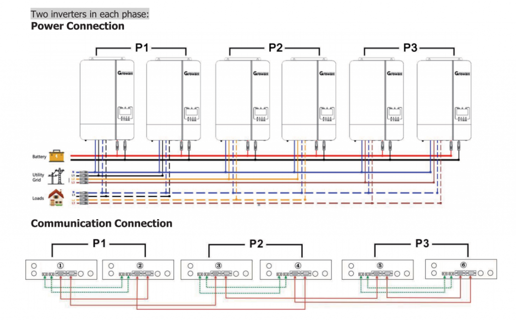
The principle of Parallel mode working
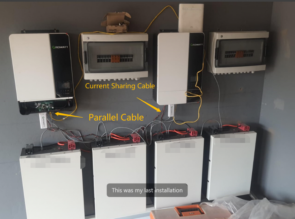
When parallel system works on same phase like 230V, you just need to connect Parallel cable and current sharing cable , then inverters will compete and produce host and slave inverter automatically. What if parallel system works on 3 phases, you need to set 23th option, and set P1,P2,P3 on all phases inverters. For inverters in parallel that working on 3 phases, when overload occurs, it can’t switch to bypass mode. For future model, it can.
For SPF 5000ES, there are different firmware version like 40.**, 41**; 67.**, 68.**; 113.**, 114.**, you can connect them in parallel, but not recommended, same version had better be used, or you may meet some troubles.
Single-phase parallel machine, just turn off the switch of a slave machine, and it will automatically shut down after a while. Three-phase will be a little troublesome, but as long as all three phases exist, otherwise the output will be cut off. Anyway, the current high-frequency machine can disconnect one. Let’s make the summary,Single-phase and three-phase, as long as there is a machine in each phase, disconnecting the others will not affect the output
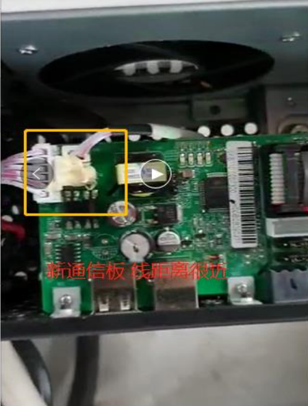
For Parallel system, if off grid inverter has newest com board below , you just can connect battery communication cable from battery into one of inverters.
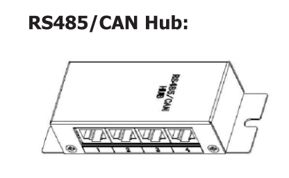
If off grid inverters have old and new com board, RS485/CAN Hub below must be used to connect inverters communication cable into HUB, Then HUB into Battery BMS.
Single Phase parallel system
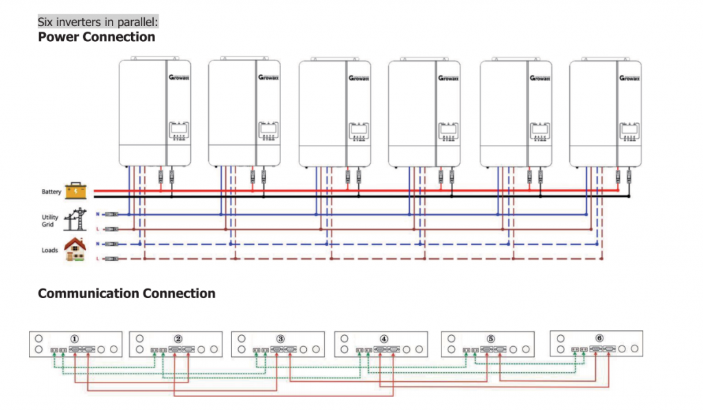
On the bottom, Green wires are current sharing cable, red ones are parallel cable
Three Phase parallel system
1.Parallel working mode
There are 3 modes for parallel mode, including Master, Slave, New.
In the initialization state, all inverters are new state. After the master-slave competition is completed, a host will be generated (the host inverter will pull down the host line, so that other inverters in the system knows that the host inverter has been generated), and then the host inverter will assign new addresses to each new inverter and make them be slave inverter; after the priority reversal occurs, the master will let it out, become a new machine, and release the master line, and other inverters in the system will judge based on the master line that there is no master in the system, and then It will also convert this inverter into a new inverter, and after waiting for about 40ms, all inverters start to resend competing data packets to compete for a new host;
The basic principle of parallel inverters is that the mains and battery inverters are not allowed to be output together. All machines either work in the inverter mode or in the mains mode;
If an inverter is added in a parallel system that already has output, the original system will not cut off the output, and the host will only control the newly added inverter to switch in the output relay (but after the inverter is ready, for example, the INV is completed and locked phase is normal);
If one machine is reduced in a parallel system that already has output, it can only be done under inverter conditions, and the SW will be turned off, and the machine will shut down normally without affecting the output of the entire system;
2. master or Slave of the competition priority on parallel mode
Under the same mode (the master and the slave are in the same mode), if the master has no mains power and the slave has mains, The priority of the master is lowered, and the master gives up and becomes a new inverter;
Different mode conditions, subject to mode priority, mode priority from high to low are mains mode, battery mode, bypass mode, standby mode, fault mode, shutdown mode;
3. New inverter query
After the inverter becomes the host, the first thing is to query the number of new inverters in the system by sending a query data packet for the new inverters. Then data packet that new inverters reply is sent to the host, and the host assigns the slave address according to different IDs. The slave address the receive new inverter data first will be higher, and the slave addresses are then accumulated in sequence, up to a maximum of 5;
4. Slave inverter query
After the host has allocated the slaves, it will query the slaves by sending the query slave data packets. After the slaves receive the query data packets, they will package the local data, and then send them to the host in stages (including the following information content: relay status Flag, Alarm Flag, Internal Status Bit, Output Current, Parallel Type, Inverter Operating Mode, Internal Status Bit 2, Mains Voltage, Inverter Voltage, Load Percentage, Battery Voltage, Current Charged to Battery, AC Charge Current , PV charging current, load active power, load apparent power, inverter voltage reference value), after receiving these data, the host will save it to the variables of the machine, and make some judgments and timing processing based on this information;
Each slave machine will also receive the data sent by other machines, and save it to the local variable, which can facilitate external communication and query;
5. Host inverter Sending data
After receiving the status data sent by the slave, the host starts to send its own information to the slave (the information sent includes: relay status flag, alarm flag, internal status bit, output current, parallel type, inverter working mode , Internal status bit 2, mains voltage, INV voltage, R-phase quantity, S-phase quantity, T-phase quantity, load percentage, battery voltage, battery SOC, total charging current of parallel system, Ac charging current, PV charging current, Load active power, load apparent power, INV voltage reference value, R-phase average active power, S-phase average active power, T-phase average active power, R-phase average apparent power, S-phase average apparent power, T-phase average Apparent power), after receiving this information, the slave will also save it to local variables, and will also make some judgments and processing according to these variables;
6. Multi-host detection
Detect whether there are inverters with the same ID in the parallel system. If the IDs are the same, the machines with the same ID will exit the host, become new machines, and compete for the host again; theoretically, there will be no machines with the same ID. Restart the entire parallel system; the generation method of the inverter ID is calculated based on the data collected from 4 different sampling ports, and there is almost no possibility that the data of the four sampling ports are the same; in theory, as long as the IDs are different, this processing is basically useless;
7. Calculation of the number of parallel machines
According to the currently received slave data, determine the current number of parallel machines, the number of slave machines, the number of output load machines, etc., and calculate the average power of each phase; the number of parallel machines sent from the host to the slave machine is calculated by this function Obtained, the increase and decrease of the number of parallel machines are calculated by this function;
The number of parallel machines can let the system know how many machines there are now, and can accumulate the number of machines in R-phase, S-phase, and T-phase respectively; these data will be sent to each machine in the system, and each phase will be based on the number of machines in its own phase. Decide whether current sharing is required when inverting the output;
8. Parallel system input status detection
According to the slave data received by the master, the current state of the mains input is judged. If some machines have mains and some do not, the mains input inconsistency alarm will be set, and the data will be sent to the slaves; the whole system will not Switch to mains mode;
9. Three-phase input phase sequence detection
According to the phase sequence error message sent by the slave, the host will reset the phase sequence error of the local unit, so the system will alarm the phase sequence error;
10. Output phase loss detection
According to the parallel type sent by the slave, the host judges whether all three phases exist. If a certain phase does not exist, it will output an alarm for phase loss and send it to the slave. It is not allowed to start the machine in the state of output phase loss; this detection method only can be carried out through the information sent from the machine;
11. System state detection
Including SW status, output status, overload status, the host detects the status of each machine in the entire parallel system, and if the status is inconsistent, the output will be cut off; these detections are also centralized detection by the host through the information sent from the slave;
12. System Battery Missing Detection
When an inverter in the system detects that the battery is not connected, the host will set the system battery is not connected, and the entire system will be set to 56Fault, and cannot be restored;
13. System BMS communication failure detection
When an inverter in the system detects that the BMS communication fails, the host will set the flag of the system’s BMS communication failure and send it to the slave, and the slave will not start charging; the host will cut whole system off when the host detects that the BMS communication fails. ;
The significance of the existence of this flag lies in the consistency control of parallel machines;
14. System PV charge detection
When it detects that an inverter with PV system exists in the system, it judges that there is PV in the parallel system, and priority actions such as SOL are operated according to the presence of PV;
In the whole system, if not all machines are connected to PV, it is difficult to judge the switching of the whole system through a certain machine. Therefore, it is necessary to detect whether the whole system is connected to PV through the host, so that consistent operation can be achieved;
15. Synchronous motion detection
a.Output relay Synchronous motion
Detect the output relay status of the output slave. If the number of relays that have been closed is the same as the number of slaves, then no synchronization and relay actions are performed; otherwise, it is necessary to judge whether the slave is locked. It needs to judge 5 times in a row to start the relay action; after that, it starts to send the command cCloseOpRlyInquiry to the slave, and the slave replies to the command. After two times, the master starts to select the point. Once the current sinpoint is in the appropriate In the range, the cCloseOpRly command is sent, and then all the machines select the point (select the point to be switched), and then perform the action of closing the relay;
B.Parallel overload detection
The master collects the overload status of the slaves. If one slave is overloaded or the master is overloaded, it considers that a synchronous overload operation is required. If the master is currently in bypass mode or fault mode, the master will change its fault code to overload. Fault (07), and the system overload fault is sent, the slave will also set itself as overload fault after receiving the system overload fault; if the master is currently in battery mode or mains mode, if the mains is normal, the bypass is enabled, And all machines have mains power, then the host will send the synchronous bypass command cSynToBypass, and then all machines will switch to bypass mode;
C.Parallel Short Circuit detection
The host collects the short-circuit status of the slaves. If one machine is short-circuited, or the host itself is short-circuited, the host will send a system short-circuit to turn all the machines into short-circuit fault mode;
D. Synchronous to bypass
The host collects the flags of the slaves switching to bypass. When all the machines meet the bypass conditions, the host sends the synchronous bypass query command twice (to check whether all the slaves exist), and after receiving the reply command, the host will Start to select the point, after waiting for the range of the corresponding point, send the instruction to bypass command, and all machines will switch to bypass mode together;
E. Synchronous battery to Utility input
The master collects the battery-to-mains flag BatToLine from the slave. If the master is in battery mode and the flag bit BatToLine is set, it will automatically enter the operation of battery-to-mains mode;
When starting the operation of converting battery to mains, first the host will send the command cAcToBatInquiry twice, when the slave receives this command, it will reply to the command cOnlineSlaveReturn, indicating that the slave is online, then the host enters the point selection mode, when the current sinpoint point value is greater than wRlyOnP, it keeps waiting, and then the master sends the command cBatToLine to the slave, and the master sends the event eScheBatToLine; the slave also sends the event eScheBatToLine after receiving the cBatToLine command; all machines start battery transfer after receiving the event eScheBatToLine When switching the power, you need to select wRlyOnP to switch.
16. Parallel current sharing problem
Under parallel conditions, the inverter reference is divided into several cases:
In the single-phase parallel state, the master sends its own inverter voltage reference value to all slaves, and the slaves control the inverter voltage according to the reference value sent by the master;
In the three-phase parallel state, one machine in each phase will send the inverter voltage reference value of the machine, and other machines will control the inverter voltage according to the inverter voltage reference value sent by this phase;
Parallel current sharing, the current sharing is sampled by the local machine, and the sampled value is added to the current loop; the parallel current sharing is equivalent to a control module, only when it is confirmed that the local machine is one of several machines in a certain phase Only one unit will join the current sharing control function, otherwise this function module will not take effect;
Under the condition of utility charging or SUB, current sharing cannot be achieved. The current method is to accumulate the output power of each machine, and then take the average value to display;
17. Parallel system communication issue
Parallel communication is based on the communication line. Each machine in the parallel system must be connected with the parallel communication line to become a parallel system; each machine in the parallel system will detect whether the CAN interruption is normal. If it is abnormal or there is no CAN interruption, it is considered that the machine is a stand-alone system, and it will operate according to the phase-locking mode of freerun under the inverter;
The loss of the communication line of the parallel machine is detected by CAN interruption. If there is no CAN interruption for a long time, it is considered that the communication line is lost, and the machine will enter 80Fault (communication abnormality of the parallel machine) and cut off the output;
if it is a three-phase parallel system and R phase just has one inverter, then after the R phase is lost, the other two phases will enter 81Fault (the host is lost). After the fault occurs, the system cannot be restored, and the entire system needs to be restarted; in view of the CAN interruption of the communication line in the case of a single machine, Parallel system detects the loss of parallel communication lines by adding the conditional judgment of the number of parallel machines. Only when the number of parallel machines is greater than 1 can it be judged whether CAN interruption occurs, otherwise the occasional CAN interruption is regarded as interference and ignored;
18. Parallel system Data initialization problem
In the parallel system, when a new machine appears, the host will send its own initialization data to the entire parallel system, and the machines in the system will compare the parameters of the machine with those of the host. If the parameters of the machine are found to be different, It will be changed to be the same as the host; in view of the possibility that the network data may be disturbed, other machines will limit the range when comparing the parameters sent by the host, and if the data is not within the range, it will be considered an error and discarded;
The data sent when the host is initialized include output priority, charging priority, output voltage, SOC point of AC to battery, equalization charging voltage, floating charging voltage, battery type, user type (APL, UPS, GEN), shutdown point SOC point , SOC point of battery to AC, EQ time, immediate EQ, EQ enable, EQ stop time, EQ interval time, EQ voltage, output start time, output end time, charging start time, charging end time;
19. Parallel system parameter set synchronize
In a parallel system, changing the parameters of one machine will change the parameters of other machines. The parameters that can be changed include output priority, charging priority, user type (APL, UPS, GEN), equalizing charging voltage, floating charging voltage, battery Shutdown point voltage (battery shutdown point SOC), output voltage, output frequency, battery type, maximum charging current, battery to AC voltage point (battery to AC SOC point), AC to battery voltage point (AC to battery SOC point), EQ time, immediate EQ, EQ enable, EQ stop time, EQ interval time, EQ voltage, output start time, output end time, charging start time, charging end time;
Hi Amos,
I´m wondering if this is really possible and in which conditions:
“If one machine is reduced in a parallel system that already has output, it can only be done under inverter conditions, and the SW will be turned off, and the machine will shut down normally without affecting the output of the entire system;”
I would like to switch off one inverter in my parallel setup but as far as I can remember the last time I tried that the whole setup switched off with an alarm. How do I disconnect one inverter while running without triggering a shutdown? Thanks in advance.
Dear Kirkdis,
Sorry for the late reply!
For your parallel system, how many inverters in parallel, is it single phase output or 3 phase output?
For example, single-phase parallel machine, just turn off the switch of a slave machine, and it will automatically shut down after a while
Three-phase will be a little troublesome, but as long as all three phases exist, otherwise the output will be cut off.
Anyway, the current high-frequency machine can disconnect one
Let’s make the summary
Single-phase and three-phase, as long as there is a machine in each phase, disconnecting the others will not affect the output
Hi Amos,
I have two SPF5000ES working in parallel, but with one Li battery.
Is it possible to connect one Li battery to the first and one Lead-Acid to the second?
And if is not possible, what if invertors are not in parallel?
The idea is to use my old Lead-Acid battery also.
Thanks in advance!
Hi Amos,
I have 2 x SPF5000ES inverters with parallel kit.
I understand the battery & AC parallel connections.
PV Connections.
1. Will the system work with PV string connected to only 1 inverter?
2. Will the system work with Inverter 1 – 5 x 555 W series connected PV Input & Inverter 2 – 4 x 550 W PV input.
Thank you,
For SPF 5000ES,
MAX input Voltage 450V
MAX input Current 18-22A( It depends on different firmware)
Please kindly advise your solar panel specification.