How to confirm if mainboard inside max Series inverter is normal
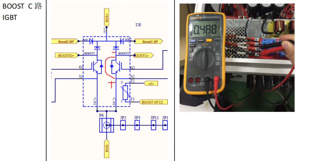
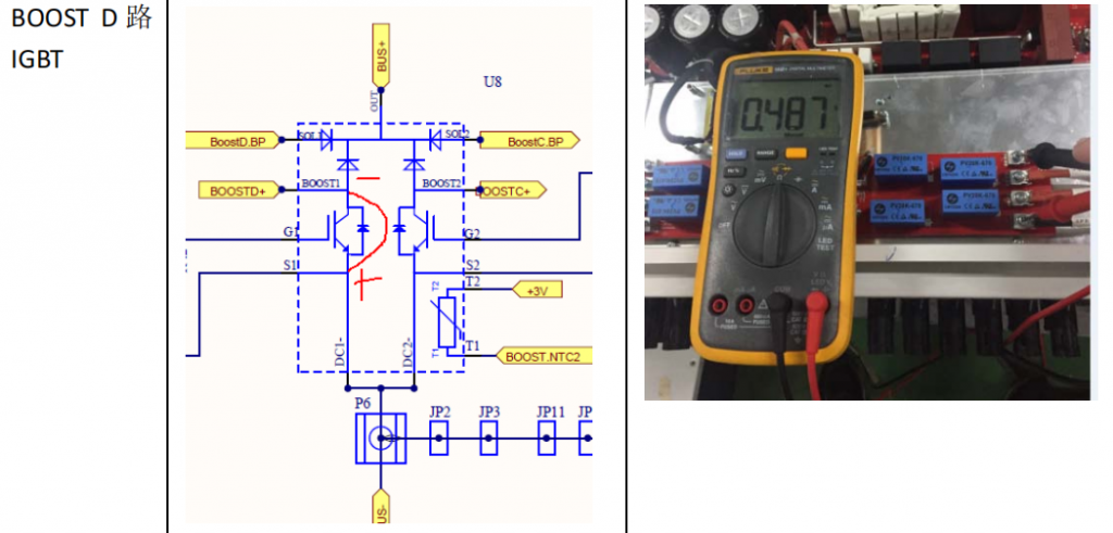
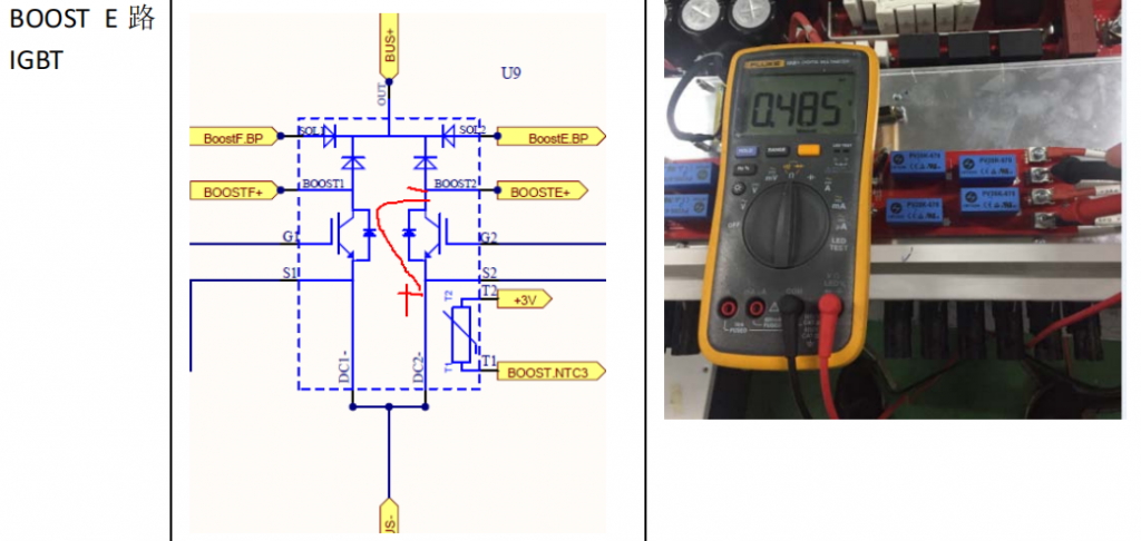
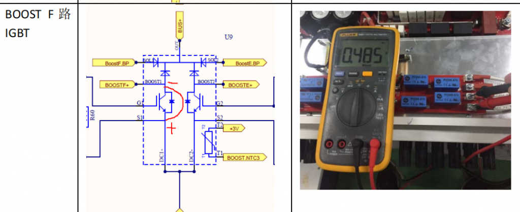
Boost Circuit and DC-AC circuit have some IGBTs, they bear large current, if mainboard can’t work, most of time, it is caused by them, so when you suspect that mainboard is faulty, you can test them.
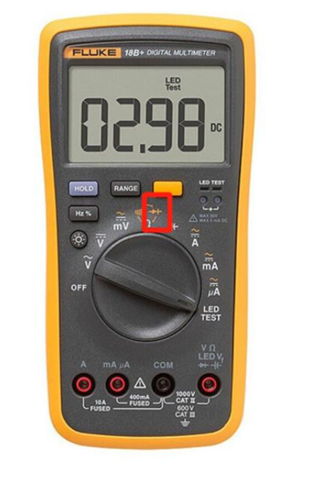
Turn to Diode position on multimeter
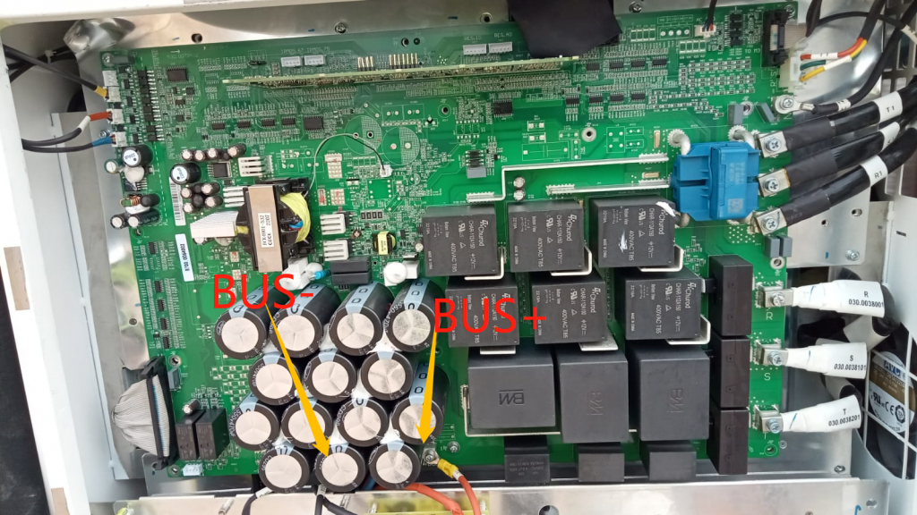
BUS+, BUS- Position
BUS Voltage is produced by BOOST Circuit on mainboard and imported into IO Board BUS+, BUS-
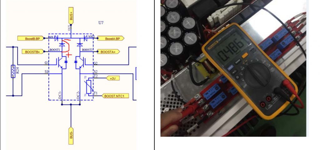
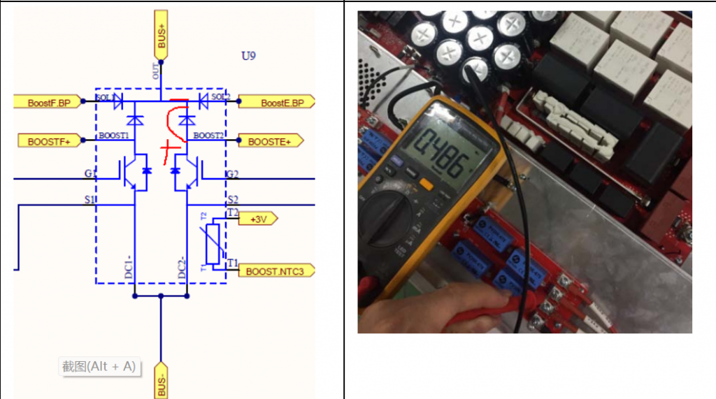
Boost circuit Testing position
1. Left Terminals on SPD board
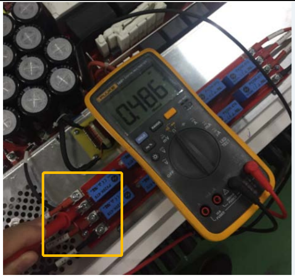
There are 4 terminals from positive , negative side of PV system on SPD board, you can test Each terminal with BUS+ like below:
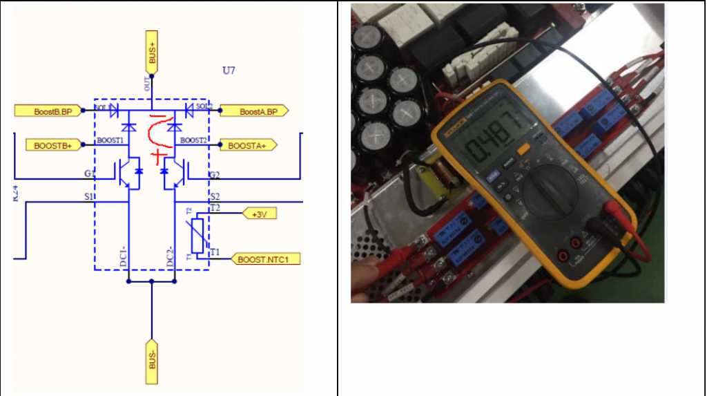
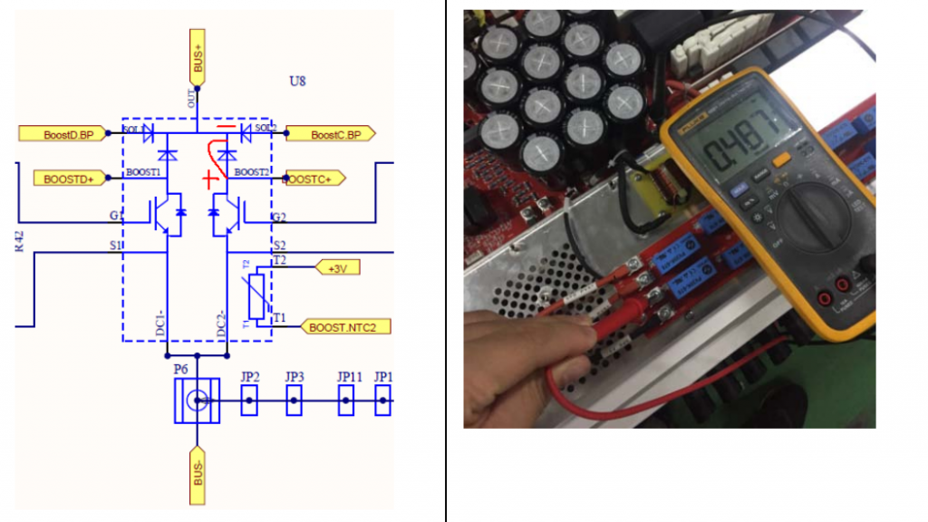
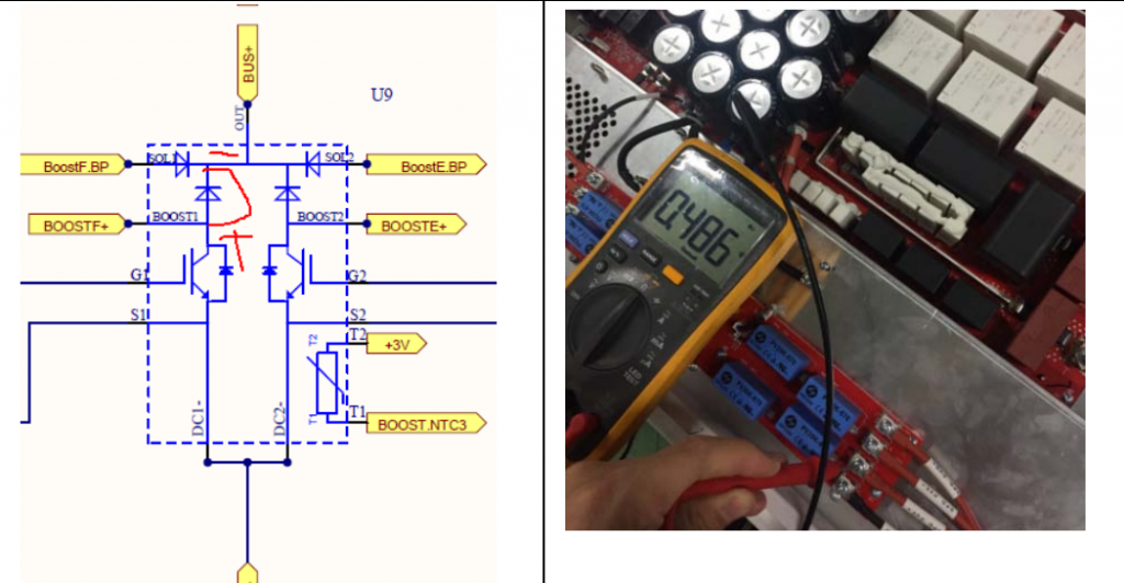
2. Right Terminals on SPD board
There are 4 right terminals from positive , negative side of PV system on SPD board, you can test Each terminal with BUS+ like below:
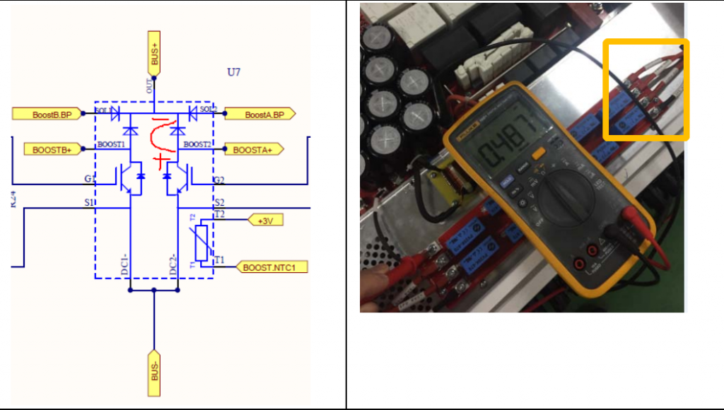
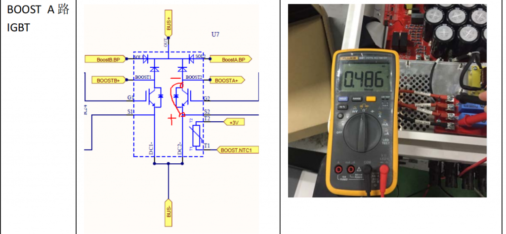
3. PV input Left Terminals on SPD board
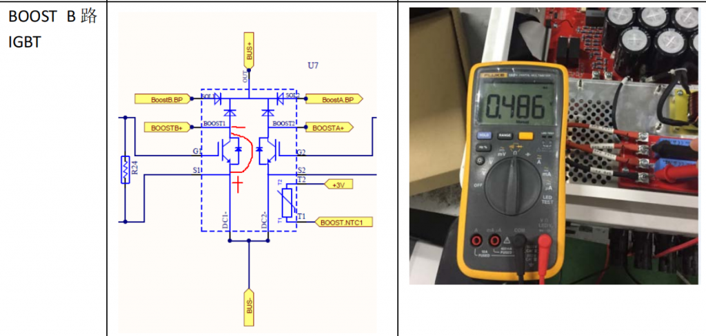
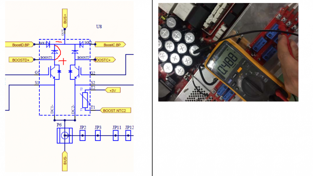
4. PV input Right Terminals on SPD board
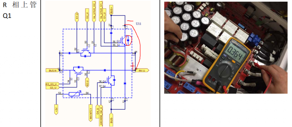
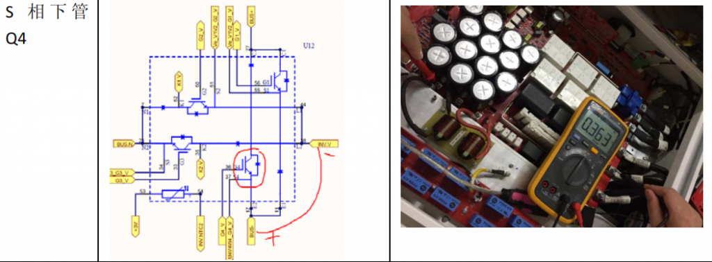
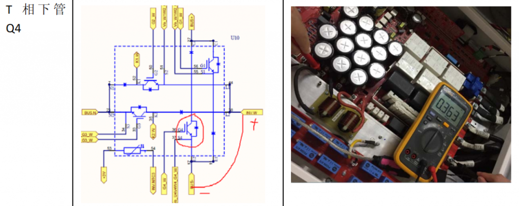
dC-aC circuit Testing position
R phase upside IGBT
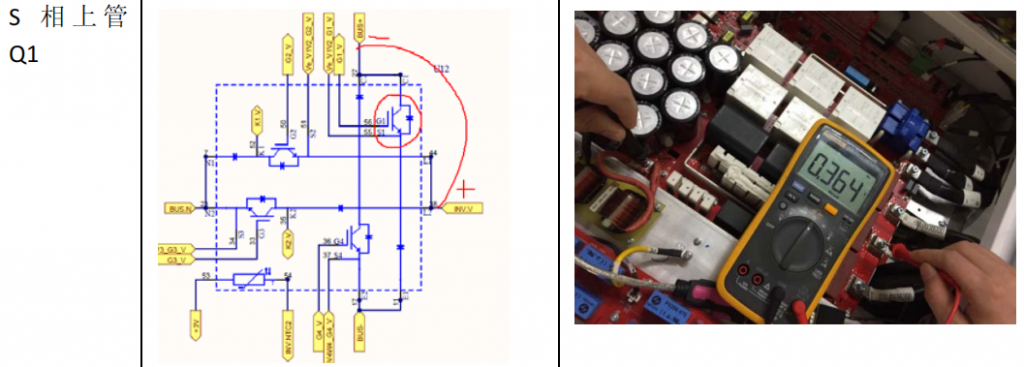
S phase upside IGBT
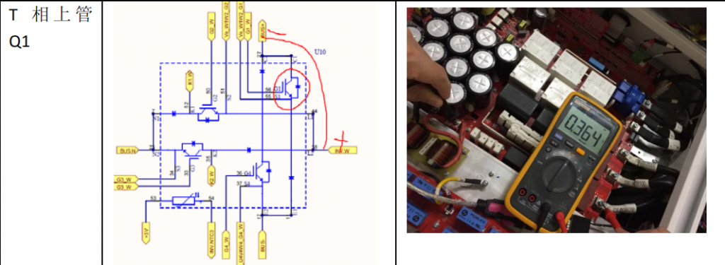
T phase upside IGBT
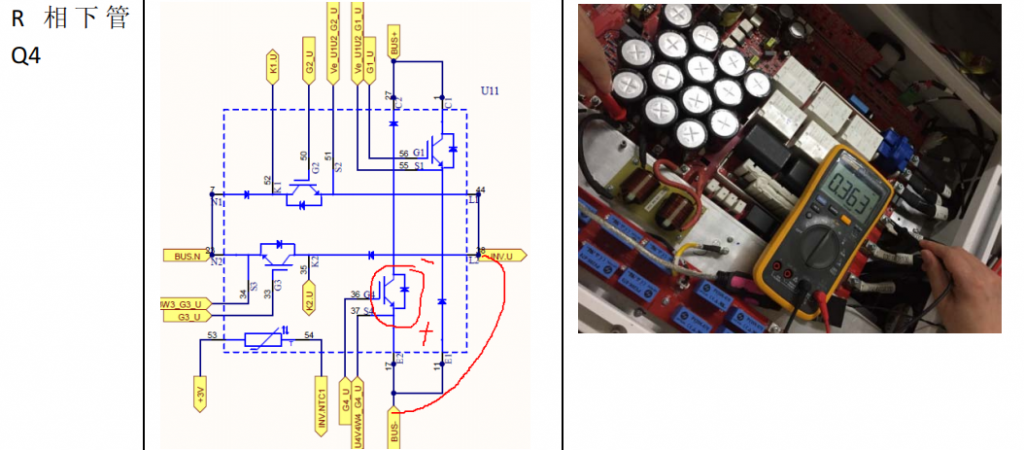
R phase Downside IGBT
S phase Downside IGBT
T phase Downside IGBT
Good day very nice blog!! Guy .. Beautiful
.. Superb .. I will bookmark your site and take the feeds also?
I’m satisfied to search out numerous useful information here within the publish, we want develop extra strategies in this regard, thank you for sharing.
. . . . .