SPF 3000-5000TL HVM PV system configuration
Many customers are confused about SPF 3000-5000TL HVM PV system configuration. This kind of model has designed Buck Circuit on MPPT board, which is used to convert PV energy into battery energy. So it is not like SPF 5000ES, which has designed Boost Circuit on MPPT board . It is used to converter PV energy into BUS voltage directly , then inverter can converter BUS voltage into AC output directly.
For this kind of inverter, battery system is necessary, so load power are supplied by battery energy instead of PV energy. Let me have metaphor, PV system is like a small pool, and flow into big pool ( like battery system) via pipeline, then big pool flows into other places like load power. So PV power is decided by battery charging power. That;s why this kind of inverter can’t connect more solar panels. Tha’t also the reason that so many people are confused why this kind of inverter just connect lower PV input power than inverter power claimed in the manual.
SPF 3000TL HVM 24V PV System Configuration
Default Charing Current
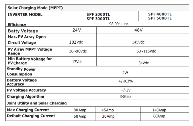
In the SPF 3000TL HVM Column, you can see Default Charging Current 60A, which means battery charging current instead of PV charging current, many clients are confused about that.
PV input Power = PV Charing Power = Battery Charing Power = 24V( Battery voltage) * Default Charging Current = 24* 60A = 1440w
Above formula, PV input Power equals PV charging Power, which equals Battery Charing Power, so you need to caculate Battery Charing Power firstly
MPPT Range
MPPT Range decides PV input range. So PV Charing Power divide by MPPT range, we can get PV input current range
MAX PV input current = PV Charing Power / Min MPPT voltage= 1440w / 30V = 48A
MIN PV input current = PV Charing Power / MAX MPPT voltage= 1440w / 80V = 18A
So PV input Current range is in the range (18, 49)
In ususal, PV input voltage = 80% PV open circuit voltage. You can caculate the PV input current based on PV input voltage
For example:
PV input voltage = 102V* 80% = 81.6v, PV input current = 1440W/ 81.6v= 17.647A
SPF 3000TL HVM 48V PV System Configuration
The caculation is the same with above.
PV input Power = PV Charing Power = Battery Charing Power = 48V( Battery voltage) * Default Charging Current = 48* 30A = 1440w
MAX PV input current = PV Charing Power / Min MPPT voltage= 1440w / 60V = 24A
Min PV input current = PV Charing Power / MAX MPPT voltage= 1440w / 115V = 12.52A
So PV input Current range is in the range (12.25, 24)
In ususal, PV input voltage = 80% PV open circuit voltage. You can caculate the PV input current based on PV input voltage
For example:
PV input voltage = 145V* 80% = 116v, PV input current = 1440W/ 116v= 12.41A
SPF 5000TL HVM 48V PV System Configuration
The caculation is the same with above.
PV input Power = PV Charing Power = Battery Charing Power = 48V( Battery voltage) * Default Charging Current = 48* 60A = 2880w
MAX PV input current = PV Charing Power / Min MPPT voltage= 2880w / 60V = 48A
Min PV input current = PV Charing Power / MAX MPPT voltage= 2880w / 115V = 25A
So PV input Current range is in the range (25, 48)
In ususal, PV input voltage = 80% PV open circuit voltage. You can caculate the PV input current based on PV input voltage
For example:
PV input voltage = 145V* 80% = 116v, PV input current = 2880W/ 116v= 24.83A
Question
If I connect many PV strings in parallel into this kind of inverter and has exceeded the MAX value, will it damage inverter?
You must make sure that your PV input voltage doesn’t exceed MAX PV open circuit voltage, based on this, even though you connect many PV strings in parallel to inverter, it has no bad effects on inverter. But excess solar energy will be wasted.