.
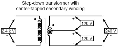
Split phase, also known as phase separation, refers to the split phase of single-phase direct current into multi-phase alternating current. Taking the power grid structure in North America and Japan as an example, the common split-phase power grid has the demand of split-phase 120v (combined phase 240v) with split-phase unbalanced load. Specifically, a split-phase grid system is composed of two live wires and a neutral wire in a three-phase power grid system. In general, a split-phase system has a first live wire l1, a second live wire l2, and a neutral wire n. The voltage of the first live wire l1 to the second live wire l2 is 202v or 240v (indicated by 240v).
裂相(split phase),又称分相,是指单相直流电裂相为多相交流电。以北美及日本地区的电网结构为例,常见的裂相电网存在裂相120v(合相240v)带裂相不平衡载的需求。具体的,裂相电网系统是由三相电网系统中的两根火线和零线构成,一般情况,裂相系统具备第一火线l1、第二火线l2、零线n,第一火线l1对第二火线l2的电压为202v或者240v(以240v说明),第一火线l1对零线n的电压为101v或者120v,第二火线对零线的电压为101v或者120v。
在逆变器对裂相电网的应用中,逆变器需要将直流电转换为裂相电网的多相交流电,例如:光伏逆变器将光伏面板发生的直流电转换为交流电并入公共电网;光储混合逆变器将光伏面板及储能电池(锂电池、铅酸电池)混合起来并入电网或者给负载馈能;交流耦合逆变器将电池(锂电池、铅酸电池)直流电并入电网或者给负载馈能。但是,一台逆变器只能输出一种电网结构的电压,比如单相电网230v,三相电网230/230/230结构,不能同时做到120v/240v电网的输出,无法满足裂相电网的输出需求。4)为满足裂相电网需求,一种常用的方式是在逆变器离网输出端口连接工频隔离变压器或者自耦变压器进行分相,这种方式下,逆变器离网运行模式下只输出240v一种电压等级,而工频隔离变压器或者自耦变压器对输出电压进行分相,从而可以得到120v和240v两种电压。然而,该常用方式中,由于采用了工频隔离变压器或者自耦变压器,导致逆变器自身体积增大,且设备整体质量较重,再加上附加变压器自身的能量消耗,使得系统整体效率也相应地降低。实现分相的另一方式是采用连接电子分相器的方式以取代工频隔离变压器或自耦变压器,然而,连接电子分相器是由开关管,电感和电容等储能设备构成的环路,为起到分相作用,其可以被看成是在原系统上增加了一级功率变换回路,又由于增加了更多的元器件,自然在变换过程中也产生了额外的能量损耗,且进一步增加了设备成本,使得系统配置过程更加繁琐。
4.综上所述,可见在现有裂相技术中,采用变压器去进行单-裂相电网转化的话,会带来转换效率低,成本偏高,设备体积及重量难以控制在家庭电器的正常范围内等缺点;而采用电子分相器去进行单-裂相电网转化的话,同样也在原来逆变拓扑后端增加了一级拓扑,增加了一级元器件以及电容电感,会引起额外能量损耗,使得成本,效能不能显著提升;且该拓扑不能带不平衡负载,属于成本高,性能差的实现方案。因此,基于逆变器的裂相拓扑电路改进,可有效规避上述裂相技术的不足。如申请号为“cn202010206115.1”的申请名称为《一种适用于分相电网的双向变换结构及输出控制方法》,就提出一种双向变换结构,满足了裂相电网对逆变器的需求,且避免了传统裂相技术的不足。
In the application of the inverter to the split-phase power grid, the inverter needs to convert the direct current into the multi-phase alternating current of the split-phase power grid. For example, the photovoltaic inverter converts the direct current generated by the photovoltaic panel into alternating current and merges it into the public power grid; the solar-storage hybrid inverter combines the photovoltaic panel and the energy storage battery (lithium battery, lead-acid battery) into the grid or feeds energy to the load; the AC-coupled inverter combines the direct current of the battery (lithium battery, lead-acid battery) into the grid or feeds the load. However, an inverter can only output the voltage of one grid structure, such as single-phase grid 230v, three-phase grid 230/230/230 structure, cannot simultaneously output 120v/240v grid, and cannot meet the output requirements of split-phase grid. 4) In order to meet the needs of the split-phase power grid, a common method is to connect a power frequency isolation transformer or an autotransformer to the off-grid output port of the inverter for phase separation. In this way, the inverter only outputs a voltage level of 240v in the off-grid operation mode, and the power frequency isolation transformer or autotransformer separates the output voltage, so that two voltages of 120v and 240v can be obtained. However, in this common method, due to the use of power frequency isolation transformers or autotransformers, the volume of the inverter itself increases, and the overall weight of the equipment is heavy. In addition, the energy consumption of the additional transformer itself reduces the overall efficiency of the system accordingly. Another way to achieve phase separation is to use the method of connecting an electronic phase splitter to replace a power frequency isolation transformer or an autotransformer. However, the connection of an electronic phase splitter is a loop composed of switching tubes, inductors, capacitors and other energy storage devices. In order to achieve phase separation, it can be regarded as adding a first-level power conversion circuit to the original system. Due to the addition of more components, additional energy loss is naturally generated during the conversion process, and the equipment cost is further increased, making the system configuration process more cumbersome.
To sum up, it can be seen that in the existing split-phase technology, if the transformer is used for single-split-phase power grid conversion, it will bring disadvantages such as low conversion efficiency, high cost, and difficulty in controlling the volume and weight of the equipment within the normal range of household appliances; and if the electronic phase splitter is used for single-split-phase power grid conversion, it will also add a first-level topology at the back end of the original inverter topology, adding first-level components and capacitors. Realize the plan. Therefore, the improvement of the split-phase topology circuit based on the inverter can effectively avoid the shortcomings of the above-mentioned split-phase technology. For example, the application number is “cn202010206115.1” and the title of the application is “A Bidirectional Conversion Structure and Output Control Method Applicable to Split-Phase Power Grid”, which proposes a bidirectional conversion structure that meets the needs of split-phase power grids for inverters and avoids the shortcomings of traditional split-phase technology.