What’s MPPT From Solar Inverter
When people talk about solar inverter, MPPT parameters always are referred. It is pretty important when in the stage of procuring, installing and commissioning solar plant.
What’s MPPT
MPPT is the abbreviation of Max Power Point Tracking, In the PV system, the output power of solar panels is determined by many factors, such as the intensity of sunlight and ambient temperature. In different environments, the output curves of solar panels are different, and the corresponding maximum power points are also different. The stronger the sunshine is, the greater the output power of solar panels are.
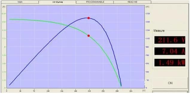
Solar panel follows I-V( Green Curve ) and P-V curve( Blue Curve). In above picture, if you hope that inverter has max output power, inverter must work on max power point on P-V curve. Why does inverter track max power point constantly, like what I referred to , P-V curve will change with sunshine intensity, temperature, shileding etc. In the morning, the voltage of max power point may be 570V, at noon it may be decline until 520V, while in the afternoon, it may rise unitl 550V. That’s why inverter needs to track the max power point continuously.
For example, the voltage of Max power point is 550V, corresponding power on the P-V curve is 200W. If inverter is working on 520V, power is approximately 190W; If working voltage is 580V, power is almost 185W. Both 190 and 185 W are not greater than 200W when working on 550V. So in the situation, inverter will have the electricity loss.
MPPT Hardware Inside inverter
How does MPPT hardware work? Before we introduce the principle, we need to figure out what Boost Circuit and Duty Ratio are. They are not like what you imagine complexly.
Boost Circuit
Boost Circuti is used to convert PV voltage into Bus voltage, then Bus voltage will be converted into AC output via DC-AC circuit. It is inverter principle. Boost Circuit can promote the output voltage.
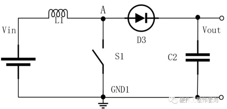
Boost Circuit contains Inductor, MOSFET /IGBT , Diode, Capacitor
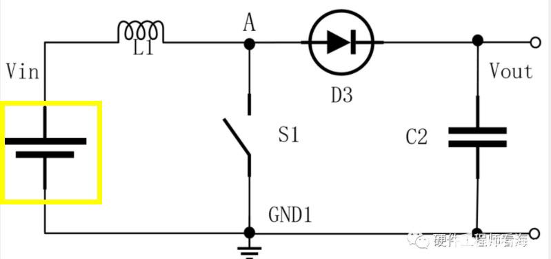

In the diagram, The power supply label respresents solar panels.

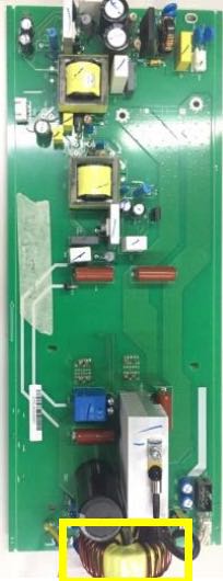
In the diagram, it is inductor label and real item is in the yellow rectangle on the right.
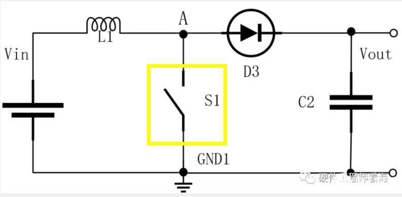
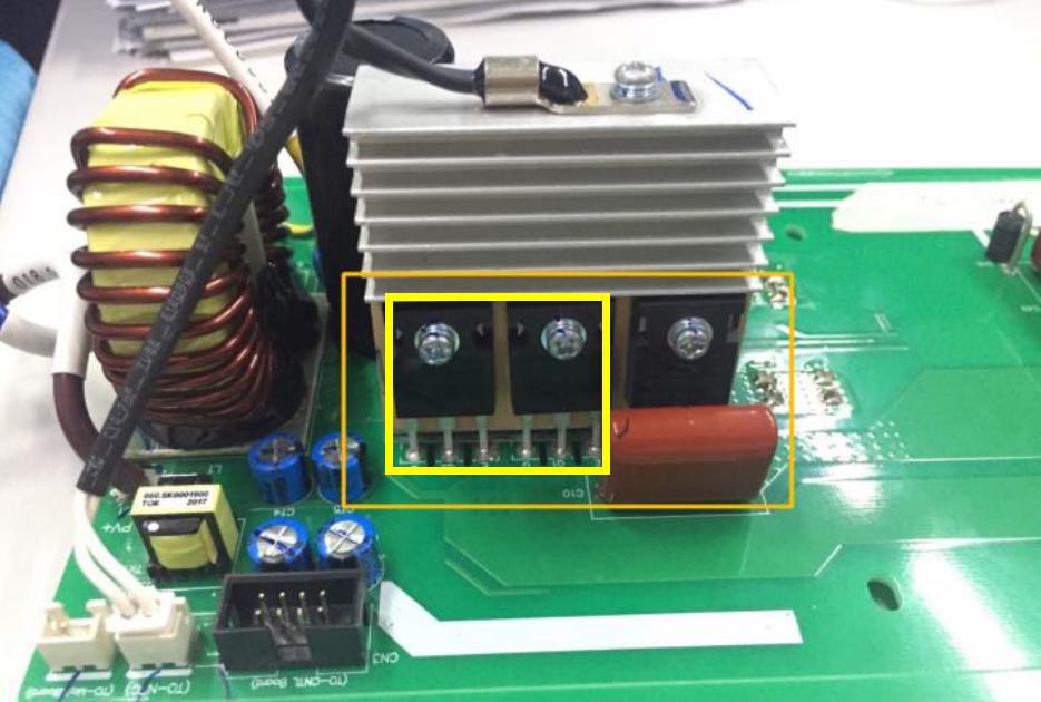
In the diagram, S1 represents mosfet or IGBT like a switch, the real item of IGBT is in the yellow rectangle on the right. In usual, mosfet or IGBT has to be attached on radiator.
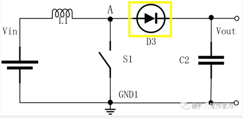
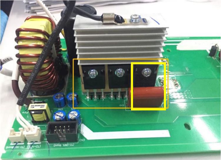
In the diagram, D3 is diode, the real item of diode is in the yellow rectangle on the right. Diode just has 2 pins.
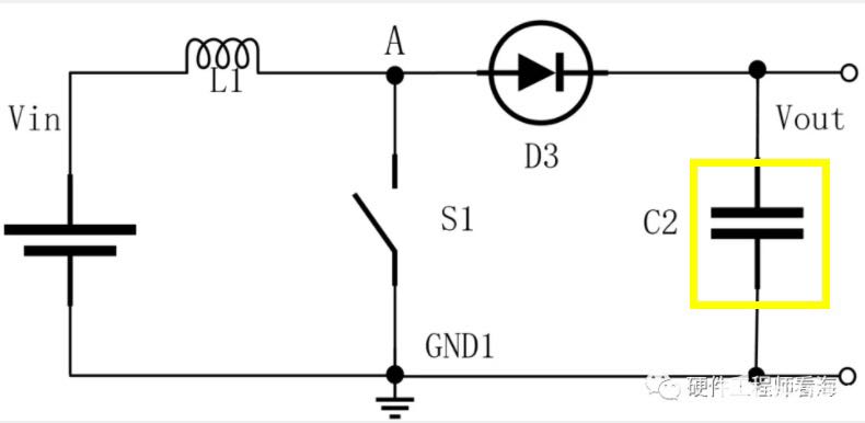
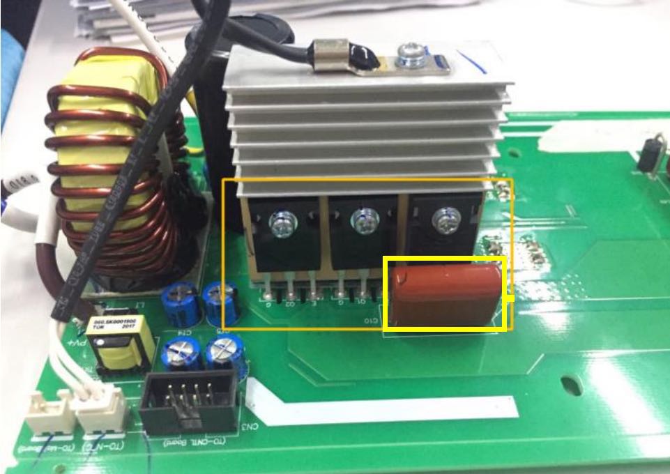
In the diagram, C2 is capacitor, the real item of capacitor is in the yellow rectangle on the right.
Duty rate
Duty rate is relate with MOSFET or IGBT we referred to , it controls the period of time of Mosfets or IGBTs that switch on or off.
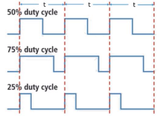
For example, the frequency is 100KHZ, which means in one seconds, MOSFET or IGBT has already switched on and off for 100,000 times ( Every time, MOSFET or IGBT finish the action of switching on and off, you can look at the picture below ). The cycle is 10μs, which contain high and low level. 50% duty cycle, it means MOSFET or IGBT switches on for half of cycle. 75% duty cycle, which means MOSFET or IGBT switches on for 3/4 cycle.
The MOSFET or IGBT that switches on or off can affect output voltage of BOOST circuit. That’s why PV voltage can be converted into higher voltage.
Boost Circuit working principle
Driving Circuit will control the time that MOSFET or IGBT switches on and off. While Driving signal from driving circuit is sent by driving chip.
MPPT Algorithm
How does inverter track the Max power point ? In the part, I will introduce main MPPT algorithm in the industry
P&O Method
It is the abbreviation of Perturbation and Observation Method.
It introduces a small variable according to the P-V curve of PV system, compares and analyzes the results after observation, and adjusts the operating point of PV system according to the results obtained from the comparison. The output P-V curve is a single-peak function curve, and the extreme value of the curve corresponds to its maximum power point, as shown in Figure below:
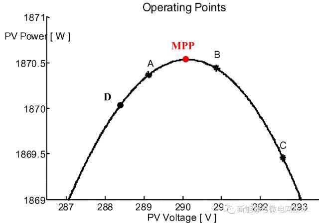
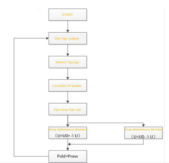
By changing the output voltage of PV ( Boost Circuit achieves this function), and sampling the output voltage and current of PV system in real time, the output power of PV system is calculated, and then compared with the out power of PV system obtained in the previous time. If it is greater, the disturbance direction is correct, and the original direction is maintained; If the power is smaller, it means that the output power of PV system declines, and the output voltage of PV system should be reduced. Such repeated disturbance, observation and comparison make the PV array finally work at the maximum power point.
The specific working process is to detect the open circuit voltage of PV system before the Boost circuit starts working. Generally, about 80% of the open circuit voltage is taken as the tracking voltage. The PV system is working near the maximum power point at this time.
When the open-circuit voltage of the PV system is U0, that is, the output power is P0, select a small variable ΔU, change its working voltage to U1, and the output power of the PV system is P1, compare the magnitudes of P0 and P1, and take ΔP=P1- P0.
When ΔP/ΔU=0, PV system works at the maximum power point; if it is not 0, when ΔP/ΔU>0, the working voltage of the maximum power point should be on the right, maintaining the disturbance direction (U=U0+ΔU) ; When ΔP/ΔU<0, the situation is reversed and the flow direction is changed (U=U0-ΔU).
In order to realize the tracking control of the maximum power point, it is necessary to change the output voltage of the PV system by changing the duty cycle of the MOSFET or IGBT, so as to achieve ΔP/ΔU=0, to control its operating point at the maximum power output point. The program flow of the interference observation method is shown in Figure below.