CAN and 485 Communication
CAN Communication
CAN is the abbrevation of Controller Area Network.
It means controller local area network, which is one of the most widely used field buses in the world. At first, CAN was designed as a microcontroller communication in the automotive environment, exchanging information between various electronic control devices in the vehicle to form an automotive electronic control network, such as in generator management systems, gearbox controllers, instrumentation equipment, electronic In the backbone system, CAN communication interface is embedded. The CAN bus is a multi-master local area network, that is, each device in the network can work in the host mode during communication.
The signal on the CAN bus is transmitted using a differential voltage. The two signal lines are called CAN_H and CAN_, and they are both about 2.5V in static state. The state at this time is expressed as logic 1, which can also be called “recessive” level. The level of CAN_H is higher than the level of CAN_L to represent logic 0, which is called “dominant” level. At this time, the level of CAN_H is usually 3.5V, and the level of CAN_L is 1.5V.
In a single network composed of CAN bus, in theory, countless nodes can be connected. In practical applications, the number of nodes is limited by the electrical characteristics of the network hardware. CAN provides data transfer rates up to 1Mbps, which makes real-time control very easy. The error detection feature of the hardware also enhances the anti-electromagnetic interference ability of CAN
The CAN communication protocol mainly describes the way of information transmission between devices. The definition of the CAN layer is consistent with the Open System Interconnection Model (OSI). Each layer communicates with the same layer on another device. The actual communication takes place in two adjacent layers on each device, and the devices are only connected to each other through the physical medium of the model physical layer. The CAN specification defines the bottom two layers of the OSI model, namely the data link layer and the physical layer. The application layer protocol can be freely defined by CAN users as any scheme suitable for a specific field. The CAN specification stipulates what kind of transmission line is used for the physical connection of the CAN interface, and how the data is transmitted, but the user can freely define the meaning of the transmitted data.

CAN bus has very superior characteristics and is widely used in distributed real-time systems. These features include:
- low cost;
- Very high bus utilization;
- Very long data transmission distance (up to 10km);
- High data transfer rate (up to 1Mbps);
- The message can be received or blocked according to the ID of the message;
- Reliable error handling and error detection mechanism;
- After the sent information is destroyed, it can be automatically resent;
- The node has the function of automatically exiting the bus when the error is serious;
- The message does not contain source or destination addresses, and only uses identifiers to indicate function information, priority information, etc.
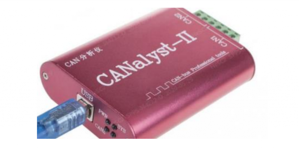
CAN Commnunication Device

USB-CAN Software ( Read monitoring data, specially for CANalyst-II CAN tool )
485 Communication
485 communication protocol is a serial communication protocol, also known as RS-485. It is a communication standard formulated by the American Electronics Industries Association (EIA), which aims to solve the problems of short serial communication distance, low communication rate, and weak interference resistance.
The 485 communication protocol adopts differential signal transmission mode, which has the advantages of strong anti-interference ability, long communication distance and high communication rate, so it is widely used in industrial automation, security monitoring, smart home and other fields
Strength
The 485 communication protocol also supports a variety of physical layer interfaces, including twisted pair, coaxial cable, optical fiber, etc. Among them, twisted pair is the most commonly used interface method, the communication distance can reach 1200 meters, and the speed can reach 10Mbps, which can meet most application requirements.
Longer communication distance
RS485 protocol can communicate within a range of 1200 meters, while RS232 and RS422 protocols have shorter communication distances.
Better anti-interference performance
RS485 adopts differential signal transmission, which can resist electromagnetic interference, radiation interference and other interference sources.
Better scalability
The RS485 protocol supports the series connection of multiple devices, which can be extended to 128 nodes.
Principle

Physical Layer
485 communication uses differential signal transmission, in which the A line and the B line respectively transmit the positive and negative levels of the same signal. This transmission method can offset the influence of interference received during signal transmission, thereby improving communication quality.
Data Link Layer
The data link layer of 485 communication uses some mechanisms to ensure the reliability of data transmission, such as parity check, CRC check, etc. In addition, some control characters are used for frame synchronization, address identification and other operations.
485 Communication Device
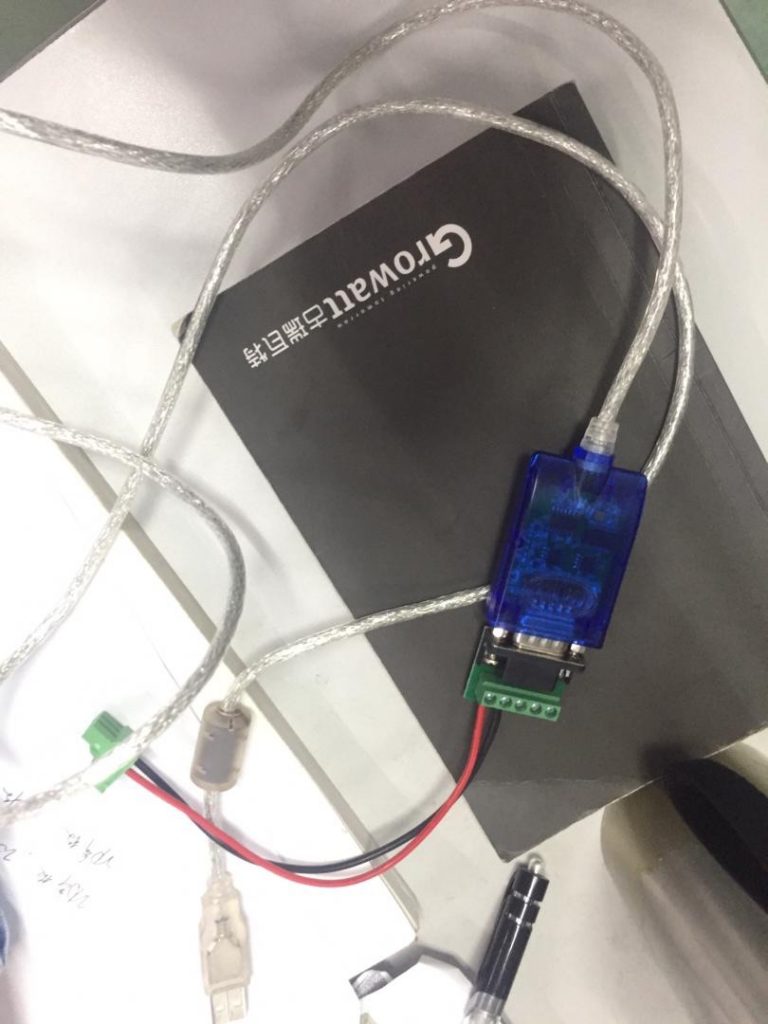
USB-485
Please note that 485 driving program needs to be installed on laptop, you can get it from device manufacturor

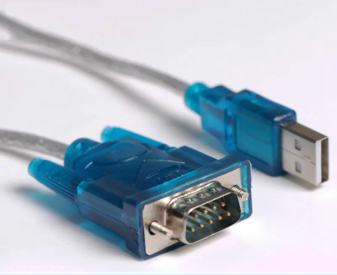
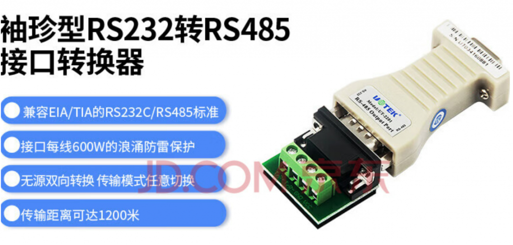
USB-232-485
You don’t install extra 485 driving program, OS will install it automatically, more convenient

