How to confirm if AXE battery Cell is abnormal
1.Check batteries and modules
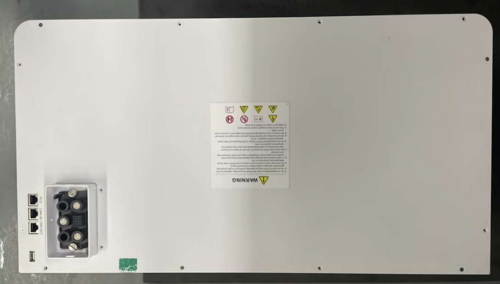
1)Remove the fixing screws of the upper cover
2) Remove the module bead and module insulation layer
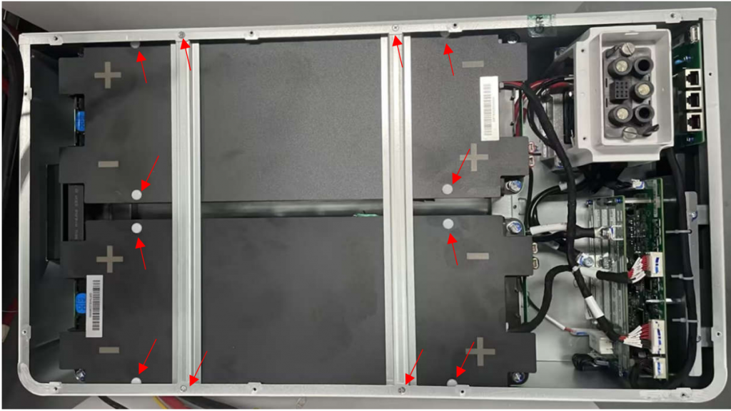
① Remove the 4 screws of the module bead and take them off. The screws are shown by the red arrows in the figure below.
② Remove the 8 plastic rivets of the module insulation layer (use a flat-blade screwdriver to lift them up to remove them)
3 ) Measure the module total voltage and cell voltage, and record
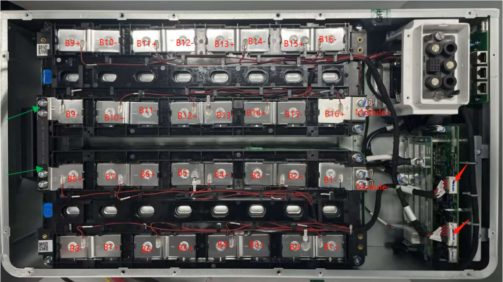
① Measure the voltage between module+ and module-
② Measure the voltage of B1~B16
③ Take a high-definition photo like the one below, save it and send it back
④ Take a high-definition close-up photo of the red arrow in the picture below and save it for transmission. Do not unplug or plug this cable yet.
⑤ Check whether the screws at the green arrow position in the afternoon are loose.
2 Troubleshoot the hardware control board function diagram
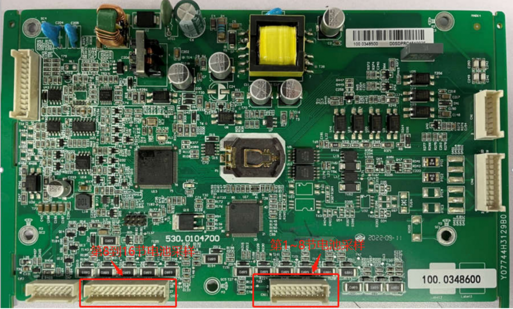
Figure1 Control board Front side
The left red rectangle shows that from 8th to 16th battery cell sampling, the right red rectangle shows that from 1th to 8th battery cell sampling
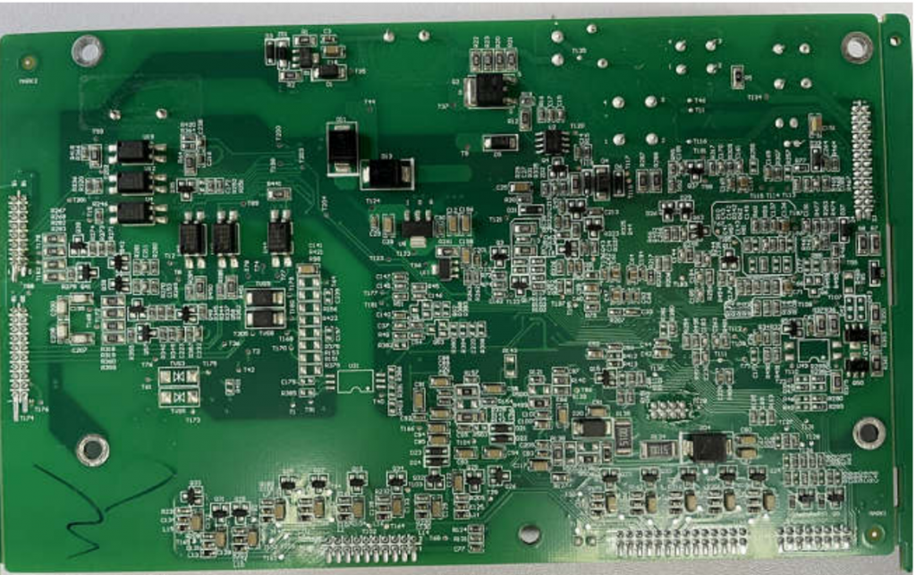
Figure2 Control board Back Side
Troubleshooting Procedures
1.Measure the actual voltage of the abnormal string of cells to see if it has dropped; simultaneously measure the voltage of all other cells except the seventh string of cells. ( we assume that 7th cell is something wrong)
2.If there is no abnormality in step (1), re-insert and unplug the single-cell battery voltage sampling connector (Figure 1), and turn on the battery to confirm if there is still malfunction. If the malfunction disappears, you can confirm that the connector connection is abnormal. If there is still a malfunction, you need to remove the PCB and perform Next step of investigation;
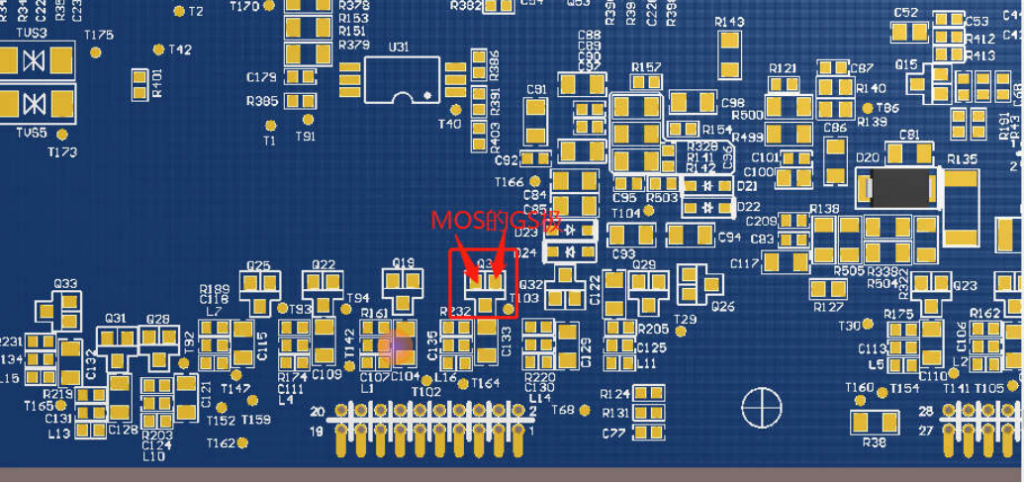
3.(After power off) Measure whether the DS ends of the abnormal string balanced MOS Q34 on the back of the control board are short-circuited, as shown in Figure 3. If not, If the circuit is normal, the device is normal. Otherwise, the MOS is abnormal. Replace the mosfet. After the replacement, power on and observe whether there is still a fault. The fault disappears. Confirm the cause of the fault and proceed to the next step if there is a fault;
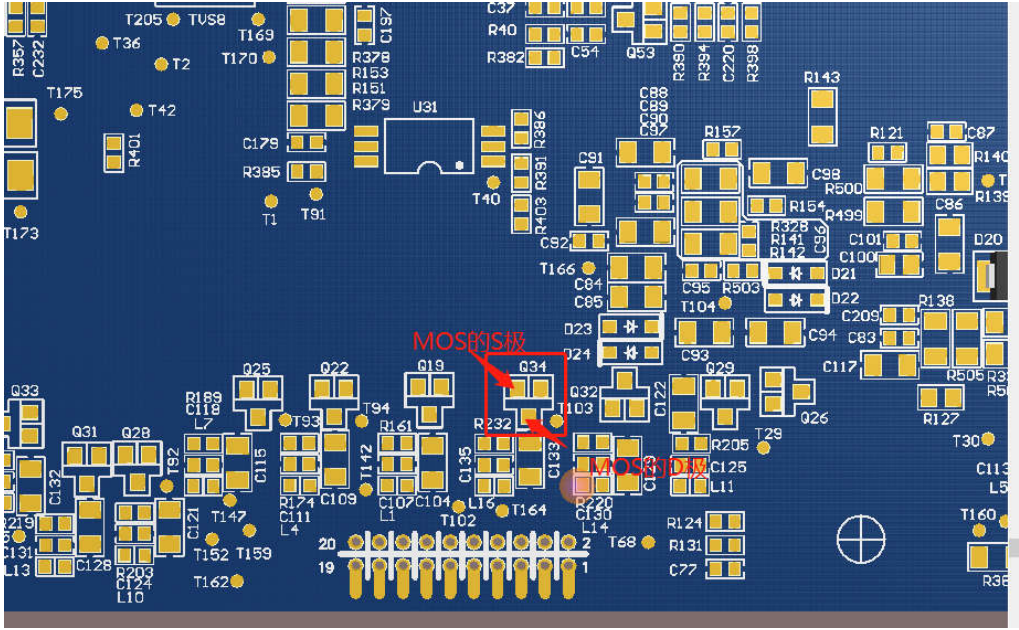
Figure3
4.(Measure the device parameters after confirming that the power is off) Use a multimeter to measure the status of each device in the abnormal series of sampling circuits; for example Figure 4 and 5, use the resistance range of a multimeter to measure whether
① the resistance of magnetic bead L16 is within 60Ω

② whether the resistance of resistor R232 is
 About 1K

③ whether the impedance of capacitors C133 and C135 is close to infinity; use the diode gear to measure whether ④ voltage regulator tube ZD20 The forward value is about 0.5v, and the reverse value is infinity; if so, the devices are normal, otherwise if there is an abnormality in the device, replace the corresponding component.

 After replacement, power on again and observe whether there is still a fault. If the fault disappears, the cause of the fault can be confirmed. If there is a fault, proceed to the next step;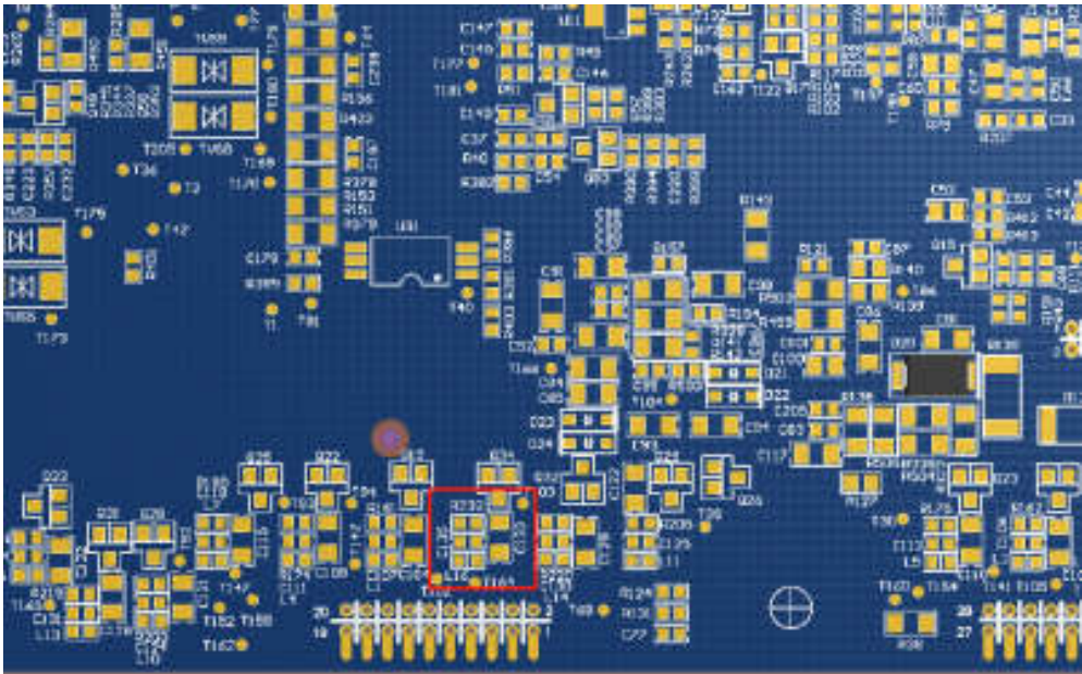
Figure4
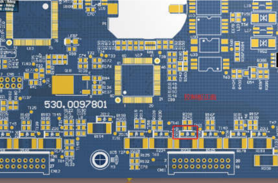
Figure5
5.Connect the analog battery core to the BMS, power on and test the voltage at both ends of the balancing resistor R236, as shown in Figure 6. If there is no voltage at both ends, then The circuit is normal. If there is voltage at both ends of the resistor, the balancing circuit is abnormal and the next step is to measure;
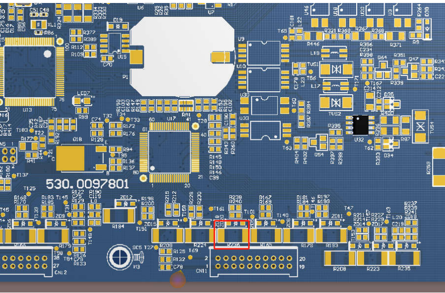
Figure6
6. Power on and test the voltage at both ends of GS of MOS Q34. If there is voltage, the output of PIN16 of the AFE chip may be abnormal.
It may be due to abnormal software control or abnormality in the chip itself, which needs to be sent back to R&D for further testing and verification; if there is no voltage,
You need to send it back to investigate the reason.