replace mainboard on max series inverter
The key of replacing mainboard is to make sure that the appearance of radiator should be cleaned. and Thermal Grease should be painted on IGBT module and keep same thickness.
procedures:
1. Disassemble SPD Board
Disassemble screws and connection wire from SPD board, then you can take out SPD Board
2. Disassemble IO Board and Seperator board
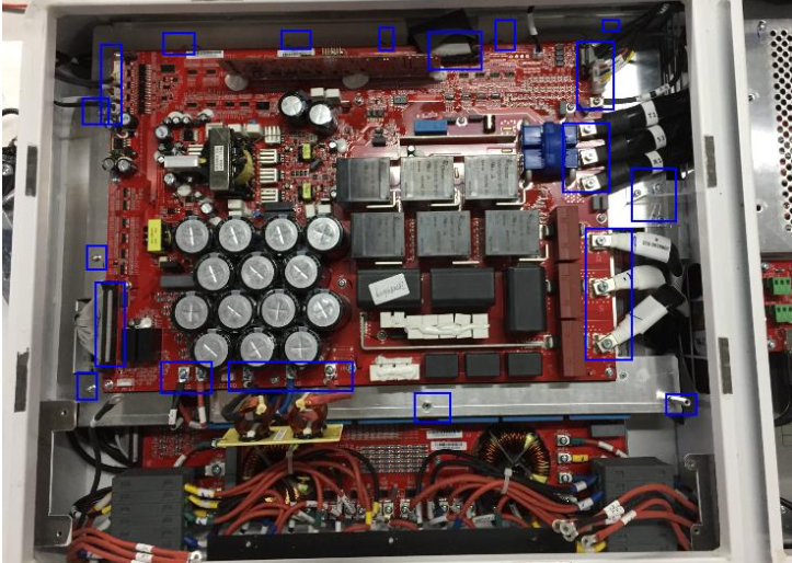
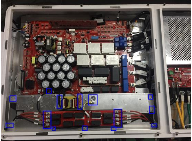
3. Disassemble these screws and connection wire, then power board can be taken out.
4. After you Disassemble power board, you will see appearance of radiator
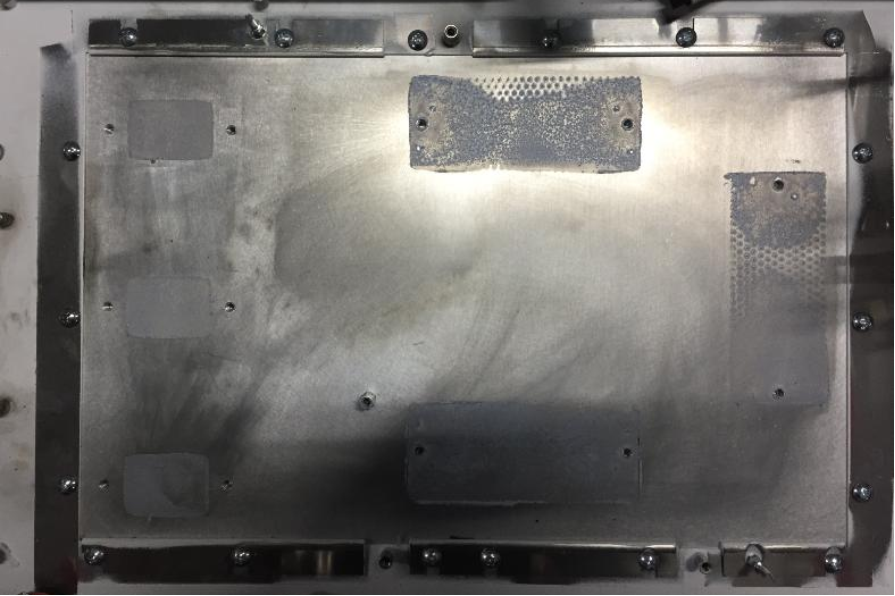
5. Clean appearance of radiator
radiator surface guide:
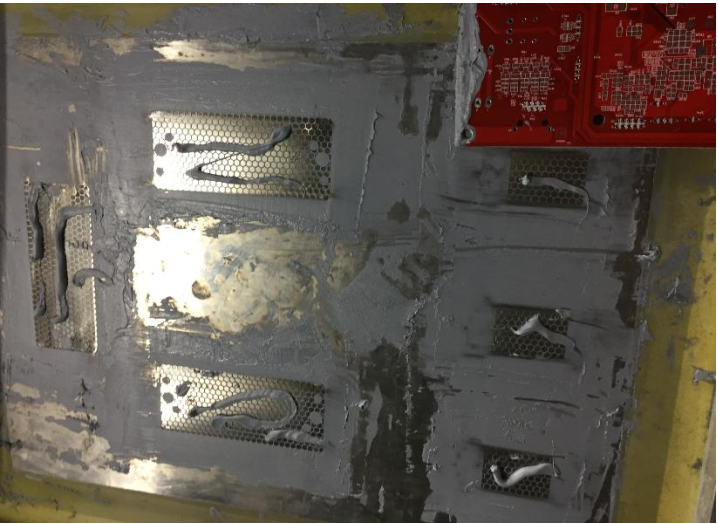
Thermal paste cleaning can use a paper towel or soft rag to wipe and appropriately use a little alcohol or water wet paper towel
to wipe with a rag like this better
Requirement:
a. The radiator appearance can’t be damaged or scraped badly
b. The radiator appearance must be wiped out, can’t leave residue stain
c. Keep the appearance smooth
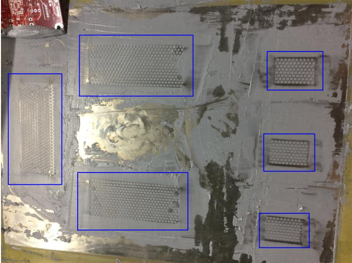
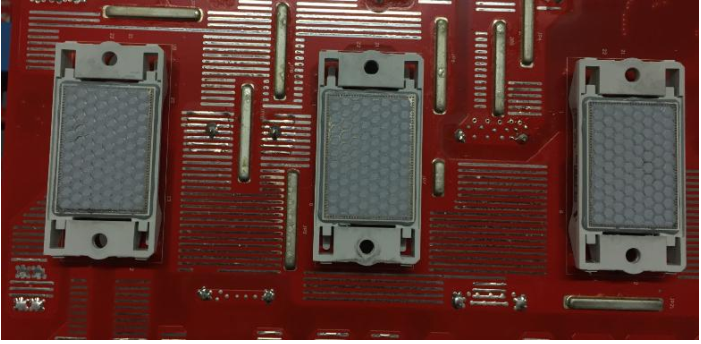
6. Thermal Grease process
1) Place metal stencil on IGBT surface and make it fixed well.
2) Thermal Grease should be squeezed out and applied on the IGBT module;
3) Then use edge of PCB board to scrape thermal paste evenly on IGBT surface. The thickness should be same with metal stencil
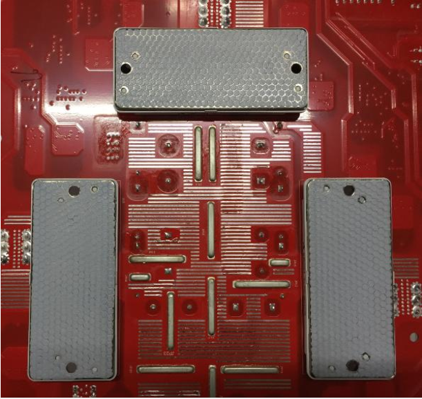
Requirement:
a. Scraped Thermal Grease must be flat and same thickness with metal stencil
b. Make sure that IGBT copper module has Thermal Grease everywhere.
After you finish scraping Thermal Grease, you can take out metal stencil, make sure that it is like below: thermal grease is scraped evenly.
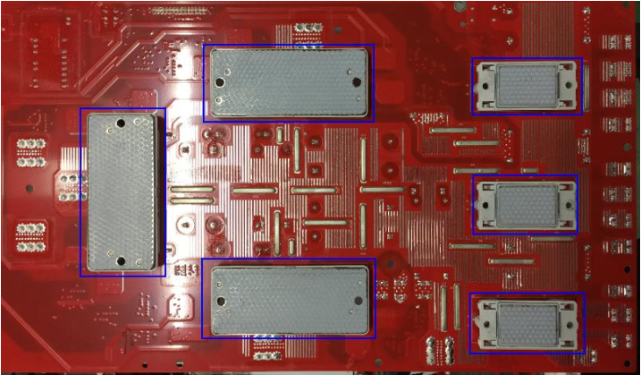
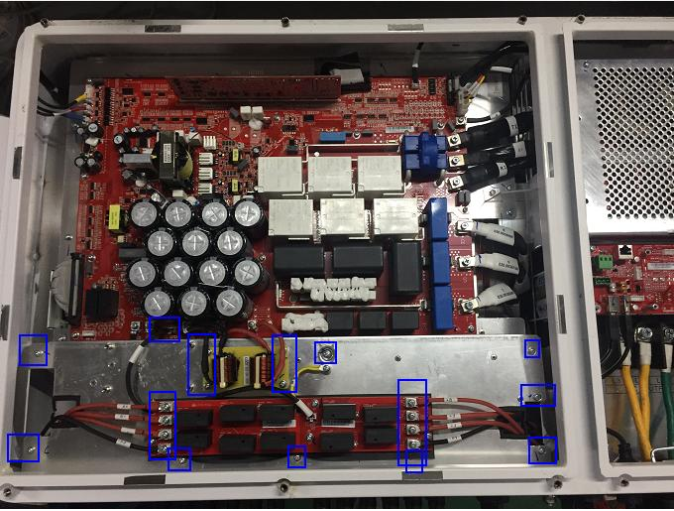
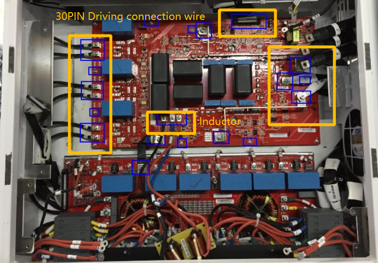
7. Assemble Power board and check it
a. Tighten 4 fixed screws in yellow rectangle on POWER BOARD
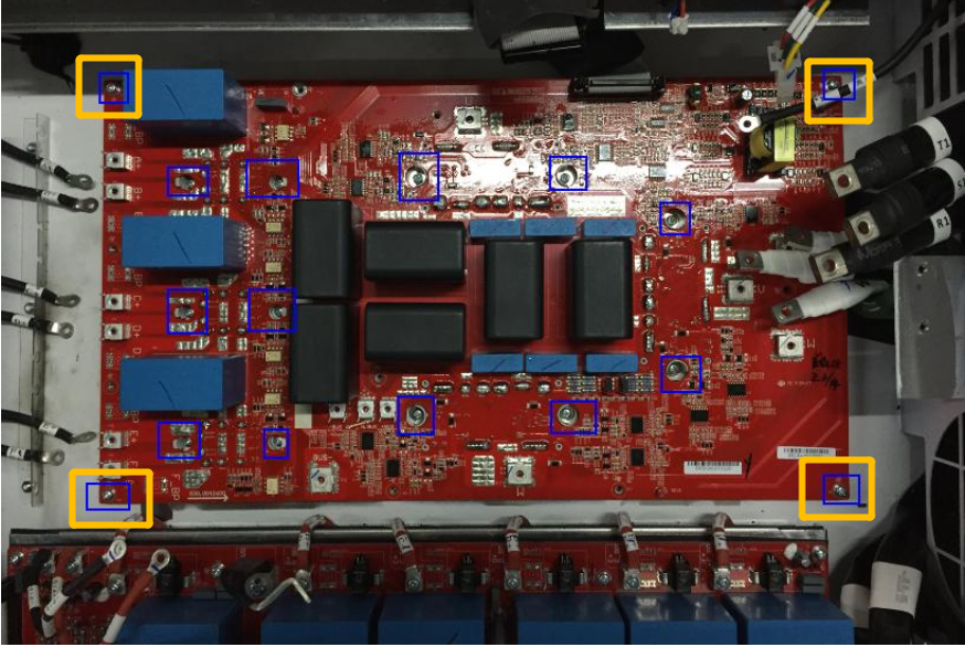
b. Tighten boost IGBT Screws
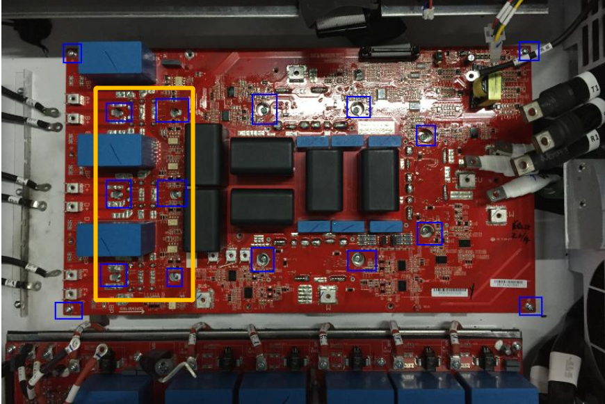
c. Tighten INV IGBT Screws
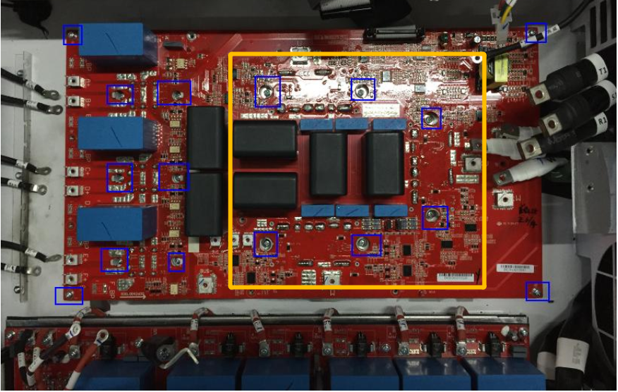
d. Connect Driving 30pin connection wire and inductor connection wire etc. Make sure that every wire has been connected well.
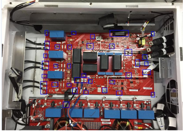
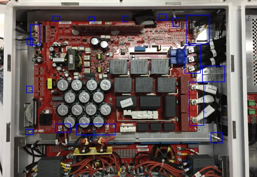
7. Assemble IO board and check it
Tighten every connection wire and screw based on the labels
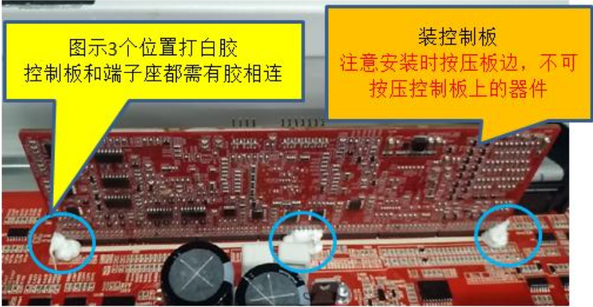
8. Assemble Control board and check it
When assembling control board, don’t touch components on control board in case they are damaged.
9. Assemble PV SPD board and check it
Tighten every connection wire and screw based on the labels