how to upload data into SCADA system on power station via Shinemaster-x
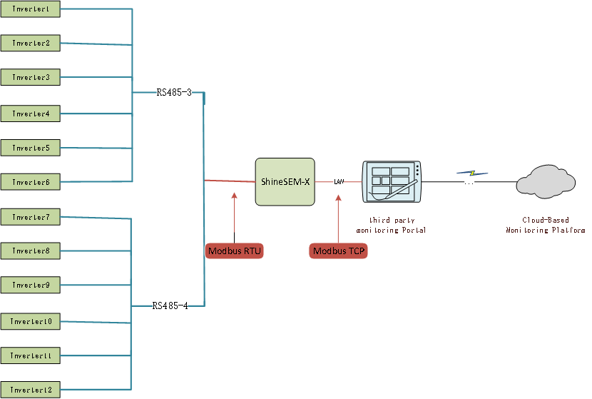
Connection topology
Introduction
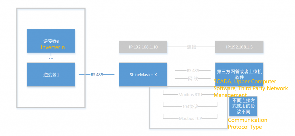
1.ShineMaster X serves as the server/slave, and third-party network administrators serve as the client/host.
1、ShineMaster-X作为服务端/从机,第三方网管作为客户端/主机。
2.The third-party network management and ShineMaster X can be connected via RS485 or Ethernet cable, and different communication protocols are used for different connection methods.
2、第三方网管与ShineMaster-X可以通过RS485连接,也可以通过网线连接,不同的连接方式,采用的通信协议不同。
3.Connected through RS485: ShineMaster X’s RS485 serves as a slave, while a third-party network administrator actively initiates register data reading and register settings for the photovoltaic equipment, using the Modbus RTU protocol.
3、通过RS485连接:ShineMaster-X的RS485作为从机,第三方网管作为主机主动发起光伏设备的寄存器数据读取和寄存器设置,采用的是Modbus RTU协议。
4.Connect via Ethernet cable: ShineMaster X still acts as a slave, while a third-party network administrator initiates commands as the host and communicates with the collector using Modbus TCP protocol or 104 protocol.
4、通过网线连接:ShineMaster-X的依旧作为从机,第三方网管作为主机主动发起命令,使用的是Modbus TCP协议或者104协议与采集器通信。
5.Third party network management reads and sets the register process for photovoltaic equipment.
5、第三方网管读取,设置光伏设备寄存器流程。
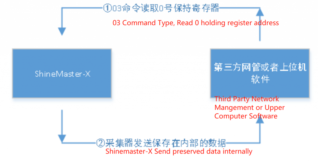
Read command:
The third-party network management reads the photovoltaic device register (03,04, command), ShineMaster X sends the photovoltaic device data saved in the collector, and ShineMaster X updates the photovoltaic device data every 1 minute, so this data is not real-time data.
If reading the data from the holding register 0 of the inverter, the process is as follows:
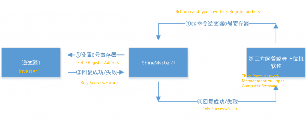
SET Command
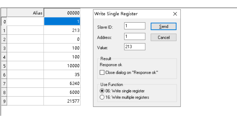
Third party network management sets the photovoltaic device register (06 command), ShineMaster X sets it in real time, and returns the result in real time.
If the value of inverter register 0 is set, the process is as follows:
Connection Process
1.Login to the built-in page, refer to manual 7.1. Login method for the built-in page
2.After logging into the built-in page, go to ->System Settings ->Wired Communication
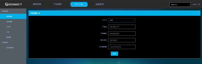
It is recommended that ShineMaster X use a fixed IP (without enabling DHCP) to prevent third-party network administrators from being unable to connect to the collector after the IP assigned by ShineMaster X changes, which requires reconfiguration.
3. Go to ->System Settings ->Server ->Third Party Network Management
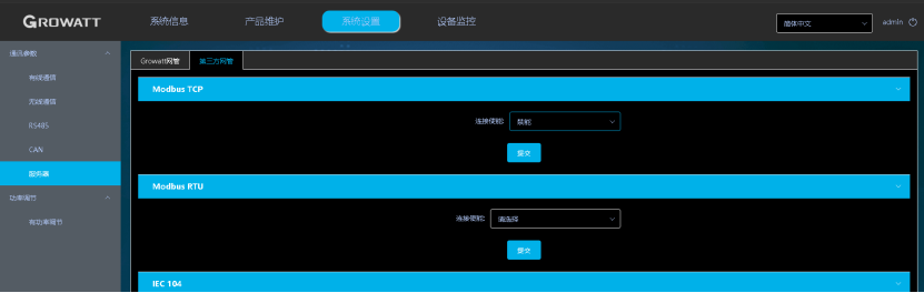
4.Enable Modbus TCP
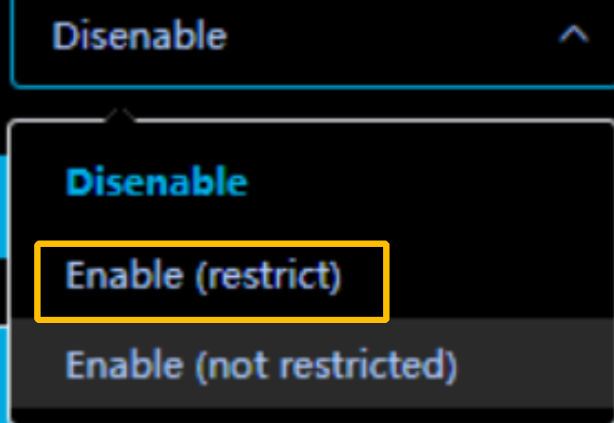
Explanation:
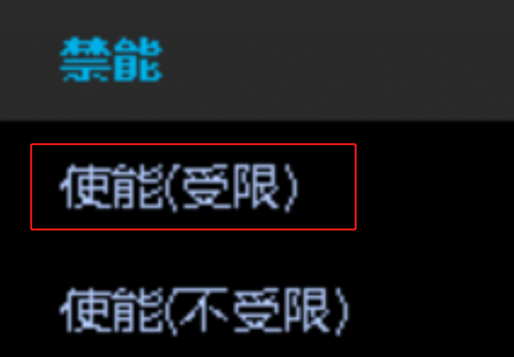
To use a fixed third-party network management IP connection, select Enable (Restricted)
If not using a fixed third-party network management IP connection, select enable (unrestricted)
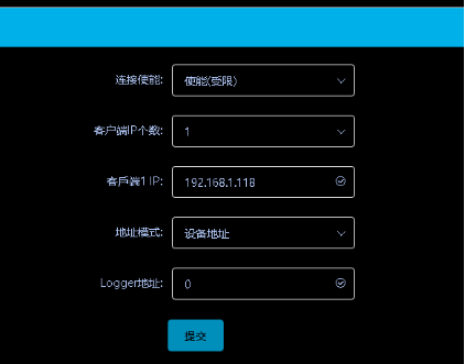
5.Taking enabling (restricted) as an example here
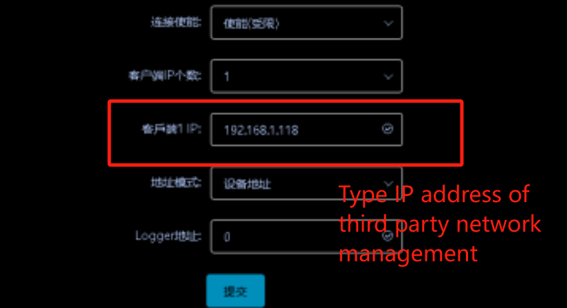
(Third party network management. Here, the Modbus TCP upper computer software tool is used to simulate the third-party network management. The IP address of the computer where the upper computer software is located is 192.168.1.118. Therefore, as the IP address of the third-party network management for the client, we fill in 192.168.1.118.)
Explanation:
If enabled (restricted), multiple third-party network management IPs can be added. If not restricted, it is recommended to connect no more than three third-party network management IPs.
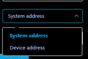
6.Address mode selection
Recommended System Address below
Explanation:

Each photovoltaic device connected to ShineMaster X has a module address and a system address. The module address is the Modbus address of the photovoltaic device, and the system address is allocated by ShineMaster X based on the order of photovoltaic device connection. The earlier the connection is made, the smaller the system address.

System address: When using a system address, third-party network administrators need to read data based on the system address of each device.

Device address: When using device addresses, third-party network administrators can directly use the module address of each device to read data, which is more intuitive and convenient.

When selecting a system address, it is required that the device address under each 485 channel cannot be duplicated, and the device address under different 485 channels can be duplicated. However, it is relatively difficult for third-party network administrators to read data, and it is necessary to check the system address of each device;
Select a device address that requires the addresses of all connected devices to be unique, regardless of whether they are on the same route 485 or not. When third-party network administrators read data, they can directly read the data through the address of the module itself.

The selection of the above two address modes should be based on the customer's own scenario.
7. Taking the device address as an example, the final configuration result can be submitted by clicking submit
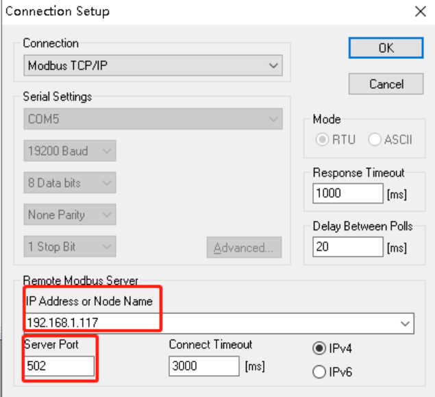
Third party network management is simulated using Modbus TCP upper computer software tool. The IP address of the computer where the upper computer software is located is 192.168.1.118. The upper computer software and ShineMaster X must be in the same network segment.
We have fixed the IP address of the collector to 192.168.1.117, and the default port is 502. Click OK to connect
1). Third party network management is simulated using Modbus TCP upper computer software tool. The IP address of the computer where the upper computer software is located is 192.168.1.118. The upper computer software and ShineMaster X must be in the same network segment.
We have fixed the IP address of the collector to 192.168.1.117, and the default port is 502. Click OK to connect
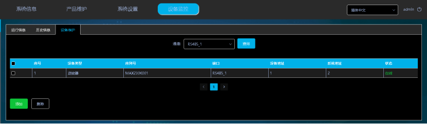
2) ShineMaster X has monitored one inverter
The device address is 1 and the system address is 2. As another inverter has already been added earlier, the system address here is 2. To demonstrate the difference between the system address and the module address.
3) Modbus TCP upper computer software tool
Since we have chosen the device address as our address mode, we are reading the inverter parameters using its own device address of 1. If I choose the system address as the address mode, here we read the old inverter parameters and use the system address assigned to the inverter.
Read the 03 section register of the inverter with address 1, read 0-14, a total of 15 registers
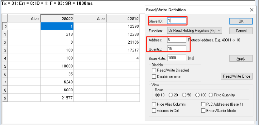
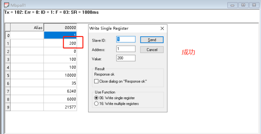
Set section 03 of inverter 1, register 1 as 200, and read to view